Keskeytykset
Osaamistavoitteet: Keskeytykset ja niiden käyttö sulautetussa laitteessa.
Tietokoneessa keskeytys on sisäinen tai ulkoinen signaali suorittimelle, joka nimensämukaisesti keskeyttää suorittimen muun toiminnan. Keskeytyksen tullessa suoritin tallentaa tilansa (ohjelman suorituksen tila, rekisterit, ym) ja siirtyy suorittamaan keskeytyksen käsittelyrutiinia. Kun käsittelijä on suoritettu, suoritin lataa tallennetun tilansa takaisin ja jatkaa ajossa olleen ohjelman suorittamista täsmälleen siitä tilasta mihin jäätiin.
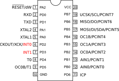
Kuvassa alla ATmelin ATtiny2313-mikrokontrollerin pinnijärjestys, jossa punaisella merkittynä kaksi ulkoista laitteistokeskeytys-pinniä (INT0 ja INT1). Näihin pinneihin voisimme kytkeä jonkun oheislaitteen lähtevän keskeytyslinjan ja näin saada kiinni sen lähettämät keskeytyssignaalit. Yleisesti ulkoisia keskeytyksiä varten on mikrokontrollereissa varatut pinnit kytkettynä fyysisesti piirin keskeytysten hallintalogiikkaan. Oheislaitteiden / komponenttien datakirjoissa on tietenkin määritelty tarkalleen millaisia keskeytyksiä ne voivat tuottaa.

Keskeytyksiä on kahta tyyppiä. Keskeytys voi olla laitteistopohjainen (keskusyksikön sisäinen oma tai oheislaiteelta tuleva) jonka aiheuttaa tyypillisesti asynkroninen (riippumaton ohjelmien ajoituksesta) tapahtuma suorittimen sisällä tai oheislaitteessa. Keskeytys siis tapahtuu ennakoimattomasti ajettavan ohjelman näkökulmasta millä hetkellä tahansa. Laitteistokeskeytyksiä tuottavat keskusyksikön sisällä esim. nollalla jakaminen (virhetilanne) tai ulkoisesti oheislaitteen viesti että tarvitsen huomiota, koska uutta dataa olisi saatavilla tai sattui virhetilanne.
Ohjelmallinen keskeytys aikaansaadaan erityisellä konekielen keskeytyskäskyllä, esim.
INT-käsky Intelin x86 -prosessoreissa. Ohjelmistokeskeytys laukaisee keskusyksikössä keskeytyssignaalin, joka käsitellään käyttöjärjestelmässä / firmiksessä samoin kuten laitteistokeskeytyssignaalit ja siten suoritetaan sille määritelty käsittelijäfunktio. Keskeytyksillä on prioriteetti. Korkeamman prioriteetin keskeytys suoritetaan ensin. Prioriteetillä on merkitystä jos vaikkapa useita eri keskeytyksiä ilmenee samaan aikaan tai kun toista alemman prioriteetin keskeytystä ollaan suorittamassa. Tällöin korkeamman prioriteetin keskeytys keskeyttää alemman prioriteetin käsittelyrutiniin suorituksen ja suorituttaa omansa ensin. Esimerkkinä sulatetuissa järjestelmissä RESET-pinnistä tulevalla laitteistokeskeytyksellä on kaikkein korkein prioriteetti. Seuraavaksi korkeammalla prioriteetillä tulevat laitteistokeskeytykset, koska ne ovat tyypillisesti aikakriittisiä. Lopuksi ohjelmistokeskeytykset, joille ohjelmoija voi asettaa haluamansa prioriteetin. Ohjelmistokeskeytyksiä siis hallitaan ohjelmoijan määrittämällä tavalla (ja nekin voivat ajaa toistensa yli).
Keskeytyksen käsittelyrutiini (engl. handler) on melkein kuin funktio, mutta sitä ei koskaan kutsuta ajettavasta ohjelmasta. Tämä on tärkeää siksi, että ennen keskeytyksen käsittelijän suorittamista täytyi prosessorin tila tallentaa ja kutsumalla käsittelijää funktiona ei tätä tallennusta tehtäisi. Rutiini ei myöskään palauta mitään arvoa, mutta siinä voidaan käyttää esimerkiksi globaaleja muuttujia tai rekistereitä välittämään tietoa. Nyt C-kielessä toki käsittelijä toteutetaan funktiona, ja RTOS:lle täytyy kertoa että funktio on siis nyt käsittelijä.
Käsittelyrutiinit ovat aikakriittisiä kahdesta syystä: ne keskeyttävät ajossa olevan ohjelman ja ne voivat ajaa toistensa yli. Tällöin koko ohjelman suoritus on helppoa (virheellisesti) blokata / estää korkean prioriteetin keskeytyksen käsittelijällä, jonka suoritus kestäisi luvattoman pitkään. Nyt TI RTOS määrittelee, että laitteistokeskeytys saisi kestää max 5 mikrosekuntia ja ohjelmistokeskeytys luokkaa 100 mikrosekuntia. Eli käytännössä vain vähäisesti koodia voidaan suorittaa käsittelijässä. Tästä syystä käsittelijät usein vain muuttavat rekisterien tai globaalien tilamuuttujien arvoja. Esimerkiksi hyvä tapa on käsittelijässä kertoa tilamuuttujan avulla, että oheislaitteella olisi uutta tietoa, ja hoitaa itse lukuoperaatio ohjelmassa käsittelijän ulkopuolella. Taas näitä tuhannan taalan ilmaisia vinkkejä. Noh, tästä lisää Tilakoneet-luentomateriaalissa..
SensorTagin keskeytykset
Seuraavaksi käymme esimerkinomaisesti läpi eri tapoja, joilla RTOS:ssa voidaan käyttää keskeytyksiä. Esittelemme sekä ulkoisia laitteistokeskeytyksiä (pinnin ja oheislaite) sekä sisäisen laitteistokeskeytyksen (UART-sarjaliikenne).
Pinni-keskeytys
Aiemmalla kappaleessa esittelime pinnin tilan muutokseen reagoivan keskeytyksen. Palataanpa asiaan..
...
// Pinnin asetukset
PIN_Config buttonConfig[] = {
   Board_BUTTON0  | PIN_INPUT_EN | PIN_PULLUP | PIN_IRQ_NEGEDGE,
   PIN_TERMINATE
};
...
// Keskeytyskäsittelijä
void buttonFxn(PIN_Handle handle, PIN_Id pinId) {
   ...
}

Int main() {
   ...
   // Asetetaan käsittelijä buttonFxn pinnille
   if (PIN_registerIntCb(buttonHandle, &buttonFxn) != 0) {
      System_abort("Error registering button callback function");
   }
   ...
}
Huomataan
Pin_Config-taulukossa pinnille on nyt asetettu vakio PIN_IRQ_NEGEDGE, joka sallii pinnin aiheuttavan keskeytyksen. Tässä keskeytys siis tapahtuu, kun pinnin tila muuttuu laskevalla reunalla eli HIGH (käyttöjännite) -> LOW (maataso). Pinnikeskeytyksen voi asettaa tapahtumaan myös nousevalla reunalla eli kun tila muuttuu LOW -> HIGH, vakiolla PIN_IRQ_POSEDGE tai jopa molemmilla reunoilla PIN_IRQ_BOTHEDGES. Keskeytyssignaalille asetamme sen käsittelijän funktiokutsulla
PIN_registerIntCb eli tässä funktio buttonFxn. Tänne funktion toteutukseen sitten tietenkin keskeytyskohtainen toiminnallisuus. Sarjaliikennekeskeytys
Viime luennoilla kävimme läpi tavan lukea sarjaporttidataa
UART_read-funktiolla niin, että taski jäi jumiin odottamaan dataa saapuvaksi (engl. blocking). Tämä ei kuitenkaan ole paras tapa odottaa dataa UART-piiriltä, koska ..no taski jäi jumiin. Nyt MCU:n näkökulmasta sarjaliikenne UART:n kautta on hidas operaatio, joten tämä ei ole hyvä tapa. Parempi tapa on asettaa sarjaliikenne toimimaan ei-blokkaavasti niin että vasta kun uutta dataa on tarjolla, keskeytys tapahtuu. Tämä hoituu UART:n asetusparametrejä muuttamalla ja tietysti laatimalla käsittelijä.
uint8_t uartBuffer[30]; // Vastaanottopuskuri
// Käsittelijäfunktio
static void uartFxn(UART_Handle handle, void *rxBuf, size_t len) {
// Nyt meillä on siis haluttu määrä merkkejä käytettävissä
// rxBuf-taulukossa, pituus len, jota voimme käsitellä halutusti
// Tässä ne annetaan argumentiksi toiselle funktiolle (esimerkin vuoksi)
tehdaan_jotain_nopeasti(rxBuf,len);
// Käsittelijän viimeisenä asiana siirrytään odottamaan uutta keskeytystä..
UART_read(handle, rxBuf, 1);
}
static void uartTask(UArg arg0, UArg arg1) {
UART_Handle handle;
UART_Params params;
UART_Params_init(¶ms);
params.baudRate = 9600;
params.readMode = UART_MODE_CALLBACK; // Keskeytyspohjainen vastaanotto
params.readCallback = &uartFxn; // Käsittelijäfunktio
params.readDataMode = UART_DATA_TEXT;
params.writeDataMode = UART_DATA_TEXT;
// UART käyttöön ohjelmassa
handle = UART_open(Board_UART, ¶ms);
if (handle == NULL) {
System_abort("Error opening the UART");
}
// Nyt tarvitsee käynnistää datan odotus
UART_read(handle, uartBuffer, 1);
while(1) {
// ikuinen looppi
}
}
Int main() {
...
Board_initUART();
...
}
Nyt, esimerkin vuoksi koodissa alustetaan RTOS:n
UART-kirjasto taskin sisällä, eikä main-funktiossa. Ajatuksena edelleenkin se, että eriytämme sarjaliikenteen omaan taskiinsa.Erona aiempaan sarjaliikenteen alustukseen on uusi asetus
params.readMode=UART_MODE_CALLBACK, joka muuttaa kirjaston toimintaa niin että aina kutsutaan vastaanottossa callback-funktiota uartFxn, aina kun dataa on saatavilla. Funktion määrittelyssä sen parametrien, vastaanottopuskurin rxBuf ja vastaanotettujen merkkien määrä len kautta pääsemme käsiksi vastaanotettuun dataan keskeytyksen käsittelijässä. Oheislaitteiden keskeytykset
Esimerkkinä oheislaitteen ulkoisesta keskeytyksestä SensorTagissa, esitellään monipuolinen MPU9250-anturi (datakirja 42 sivua). Anturiin on integroitu asentoanturi (engl. gyro), kiihtyvyysanturi (engl. accelerometer) ja magnetometri. Anturia voidaan käyttää myös kompassina.
MPU9250 toimii keskeytyksen avulla siten että SensorTagiin on kytketty sen ulkoinen keskeytyslinja
Board_MPU_INT (otsikkotiedostossa CC2650STK.h). Keskeytys otetaan siis käyttöön ihan samoin kuin pinnikeskeytys yllä. Esimerkissä alla opimme lisäksi kontrolloimaan milloin ulkoisia keskeytyksiä sallitaan tapahtuvan.
// RTOS-muuttujat MPU9250-pinneille
static PIN_Handle MpuHandle;
static PIN_State MpuState;

// MPU9250-pinnien asetukset
static PIN_Config MpuConfig[] = {
    Board_MPU_INT | PIN_INPUT_EN | PIN_PULLDOWN | PIN_IRQ_DIS | PIN_HYSTERESIS,
    PIN_TERMINATE
};

// Käsittelijäfunktio
Void MpuFxn(PIN_Handle handle, PIN_Id pinId) {
      ...
}

Void sensorTask(UArg arg0, UArg arg1) {

   // Sallitaan MPU9250-keskeytys nousevalla reunalla
   PIN_setInterrupt(MpuConfig, PIN_ID(Board_MPU_INT) | PIN_IRQ_POSEDGE);
   ...
   // Kielletään MPU9250-keskeytykset
   PIN_setInterrupt(MpuConfig, PIN_ID(Board_MPU_INT) | PIN_IRQ_DIS);
}

int main(void) {
   ...
   // Otetaan käyttöön MPU-keskeytyspinni
   MpuHandle = PIN_open(&MpuState, MpuConfig);
   if (MpuHandle == NULL) {
      System_abort("Pin open failed!");
   }

   // Asetetaan keskeytyksen käsittelijäfunktio
   PIN_registerIntCb(MpuHandle, &MpuFxn);
   ...
}
Puretaanpas tämä esimerkki. Nyt
main-funktiossa otamme keskeytyslinjan käyttöön ohjelmassa ja asetamme keskeytykselle käsittelijäfunktion MpuFxn.Pinnin konfiguraatiossa
MpuConfig on uusi vakio PIN_IRQ_DIS (engl. disable) kertomassa, että pinnin aiheuttamat keskeytykset ovat lähtökohtaisesti pois päältä. Joten, kun haluamme vastaanottaa keskeytyksiä (esim taskissa) tarvitsemme funktiota PIN_setInterrupt asettamaan keskeytykset päälle, tässä vakiolla PIN_IRQ_POSEDGE. Tyypillisesti keskeytys kannattaa laittaa päälle viimeisellä mahdollisella hetkellä koodissa, jotta keskeytykset eivät sotke ohjelman toimintaa ennenkuin niitä oikeasti halutaan.Esimerkissä on vielä
sensorTask:n toteutuksessa mukana keskeytyksen asetus päälle PIN_setInterrupt-funktiolla. Tällä tavoin, asettamassa keskeytyksiä päälle ja pois päältä, voimme ohjelmallisesti niitä. Ajastimet
RTOS:n tarjoaa myös ajastimen
Clock-kirjastossa, jolla voimme toteuttaa ajastettua tapahtumia eli keskeytyksiä tietyin väliajoin. Esimerkiksi, voisimme ajastimen avulla kerran sekunnissa lukea anturidataa, kommunikoida oheislaitteen kanssa tai vilkuttaa lediä. Aiemmassa tilakonemateriaalissa olikin tästä jo esimerkki, eli muutimme tilakoneen tilaa kerran sekunnissa niin, että sen seurauskena luettiin anturidataa ja tulostettiin uudet mittausarvot näytölle. Esimerkki kertoo meille enemmän kuin tuhat sanaa.
...
#include <ti/sysbios/knl/Clock.h>
...

// Kellokeskeytyksen käsittelijä
Void clkFxn(UArg arg0) {

   // Esimerkki-tyyliin älä tee näin, koska todella hidas
   sprintf(str,"System time: %.5fs\n", (double)Clock_getTicks() / 100000.0);
   System_printf(str);
   System_flush();
}

int main(void) {

   ...
   Board_initGeneral();

   // RTOS:n kellomuuttujat
   Clock_Handle clkHandle;
   Clock_Params clkParams;

   // Alustetaan kello
   Clock_Params_init(&clkParams);
   clkParams.period = 1000000 / Clock_tickPeriod;
   clkParams.startFlag = TRUE;

   // Otetaan käyttöön ohjelmassa
   clkHandle = Clock_create((Clock_FuncPtr)clkFxn, 1000000 / Clock_tickPeriod, &clkParams, NULL);
   if (clkHandle == NULL) {
      System_abort("Clock create failed");
   }
   ...
}
Jälleen kerran meillä on käytössä asetustietorakenne, tässä
Clock_Params. Jäseneen period asetamme halutun ajan kellojaksoina. Muistellaan aiempaa materiaalia, jossa kerrottiin että yksi tikitys vastaan meidän ajassa noin 10 mikrosekuntia. Nyt asetamme periodiksi
100000, jolla saadaan ajastinkeskeytys noin yhden sekunnin välein. Tässä epätarkkuus johtuu siitä, että Clock-kirjaston kello on toteutettu ohjelmallisesti ja siten sen keskeytykset ovat ohjelmistokeskeytyksiä. Ajettuamme yo. esimerkkiohjelmaa, nähdään että ajan laskenta heittelee muutamia kymmeniä mikrosekunteja suuntaan taikka toiseen. Noh, tämä on riittävä tarkkuus meille ihmisille. Asetustietorakenteen jäsenellä
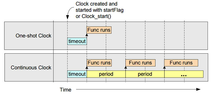
startFlag voidaan asettaa kello käyntiin heti Clock_create-kutsusta (startFlag=TRUE) tai erikseen käynnistettäväksi myöhemmin Clock_start-kutsulla (startFlag=FALSE). Kello pysäytetään Clock_stop-kutsulla. Näissä kutsuissa tarvitaan parametriksi kahva. Clock_create-kutsussa on myös meille uutta. Kutsun ensimmäinen parametri on keskeytyskäsittelijä, tässä funktio clkFxn. Funktion ideana on osoittaa miten ohjelmistolla toteutettu kello toimii. Tässä muistetaan, että tulostus konsoli-ikkunaan, on todella hidas operaatio (MCU:n mielestä), joten tässä rikomme kirkkaasti sääntöä ettei keskeytyksen käsittelijän suoritusajan pitäisi olla kovin pitkä. Noh, annetaan anteeksi nyt, koska halusimme mitata ohjelmistokeskeytysken epätarkkuuden. (Parempi tapa tehdä sama asia olisi tallettaa kellonaika globaaliin muuttujaan ja taskissa tulostaa se konsoli-ikkunaan tilamuuttujan avulla. )Clock_create-kutsun toinen parametri, timeout (tässä 1s), kertoo ajastimelle kuinka monta tikitystä se odottaa ennen ensimmäistä keskeytystapahtumaa. Tässä ideana on, että voidaan myös toteuttaa kertakäyttöisiä (engl. one-shot) ajastimia. Näissä kelloissa Clock_params-rakenteen period-jäsen asetetaan nollaksi ja tähän timeout-argumenttiin haluttu aikaviive. Clock-kirjaston kaksi erityyppistä kelloa.

Kirjastolla voidaan luoda ohjelmaamme useita yhtäaikaisia kelloja, tarvitsee vain esitellä kahva per kello sekä asetusparametrit ja luoda kellot jokainen
Clock_create-kutsulla. Tämä ei tosin ole erityisen hyvä tapa, vaan parempi on toteuttaa yksi kellokeskeytys ja siinä laskea montaa aikaviivettä yhtaikaa. Lisäksi kirjasto esittelee meille jo tutun
Clock_tickPeriod-muuttujan, joka kertoo kuinka monta mikrosekuntia yksi tikitys on. Clock_getTicks-kutsulla saadaan selville ohjelman käynnistyksestä kulunut aika tikityksinä.Reaaliaikakello
Kaiken tämän päälle vielä RTOS tarjoaa myös reaaliaikakelloa varten kirjaston
Seconds, joka pyörii meidän ihmisten ajassa. Ainoa varjopuoli tässä on, että meidän pitää itse alustaa kello kääntämällä viisarit haluttuun aikaan ennen sen käyttöönottoa. Luotamme jälleen esimerkin voimaan.
#include <ti/sysbios/hal/Seconds.h>
...
Void clkFxn(UArg arg0) {

   time_t nyt = time(NULL);
   struct tm *aika = localtime(&nyt);
   System_printf("Kello on %02d:%02d:%02d\n", aika->tm_hour+3, aika->tm_min, aika->tm_sec);
   System_flush();
}

Int main() {
   ...
   // Asetetaan reaaliaikakellon aloitusaika
   Seconds_set(1475578882); // Jännempi argumentti..
   ...
   }
Huomataan ensin
main-funktiossa kutsu Seconds_set, jolla kello asetetaan haluttuun aikaan. Nyt homma menee mielenkiintoiseksi (noo.. jonkun mielestä ihan varmasti!) Tässä kellonaika annetaan Unix-aikana, eli kuluneina sekunteina sitten 1. tammikuuta 1970 00:00:00 UTC, joka ilmaistaan 32-bittisenä kokonaislukuna. Netistä löytyy useita sivustoja, jotka laskevat kuluneet sekunnit valmiiksi, esimerkiksi Epoch converter (Kurssin henkilökunta ei ole missään kaupallisessa suhteessa mainittuun sivustoon). Nyt selviää, että esimerkissä yllä käytetty luku 1475578882 vastaa kellonaikaa 4. lokakuuta 2016 11:01:22 GMT.
Funktiossa clkFxn tulee myös uusia asioita, kun käytämme time.h-standardikirjastoa. Kirjasto tarjoaa funktion
time(NULL), jolla voimme kysyä kuluneen reaaliajan 32-bittisenä kokonaislukuna. Lisäksi time-kirjasto tarjoaa joukon funktioita joilla sekunnit voidaan muuntaa luettavampaan muotoon. Yllä localtime-kutsulla täytämme struct tm-tietorakenteen, jonka avulla saamme irti erikseen kuluneet tunnit, minuutit ja sekunnit.Yllä joudumme vielä asettamaan aikavyöhykkeen varsin typerästi
tm_hour+3.Hox! Seconds-kirjasto ei ole käytettävissä CCS Cloud-ohjelmointiympäristössä ohjelmoidessa.
Lopuksi
RTOS abstrahoi keskeytysten käytön varsin yksinkertaiseksi käsittelijän kirjoittamiseksi funktiona. Emme edes välttämättä tiedä, toimiiko kirjasto keskeytyspohjaisesti vai onko kyseessä vain ohjelmafunktio. Tätä varten on syytä lukea kyseisen kirjaston dokumentaatiosta mistä on kyse. Muutoin saatamme tietämättämme toteuttaa liian raskaan käsittelijän keskeytykselle.
Anna palautetta
Kommentteja materiaalista?