NOTE: The project is found at Github
Session 2
Starting up
Just like in the previous session, start by downloading the virtual machine. If you are using the same computer, you can simply open the one you created earlier.
The virtual machine can be found through its Lovelace link.
Next, get the course repository using one of the following options:
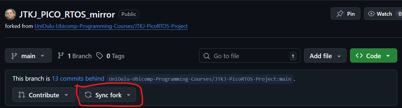
If you forked the repository in Session 1 (you have your own version of the repository under your GitHub account), clone your own repository. There have been some updates since Session 1, so remember to click the Sync fork button before cloning it.
If you did not fork the repository in Session 1, follow the same steps as in Session 1 to download the repository to your computer: Session 1 - Option 2: Download the folder to your computer.
After setting up the virtual machine and obtaining the course repository, please fill the attendance form.
JTKJ HAT
This time, you have received a box containing the board’s HAT (Hardware Attached on TOP), a custom-designed and fabricated board created at the Center for Applied Computing (CAC) for this course. The HAT includes the Raspberry Pi Pico that you worked with during the previous session. We have also included an SSD1306 OLED display that you should attach to the HAT. All information about the device has already been presented during the lectures and in section 8 (peripherals) of the Lovelace documentation.
IMPORTANT NOTE: This is a self-fabricated board and does not yet include additional protection, so handle and transport it carefully. When transporting it, remove the OLED display and place ALL parts in the box. Do not apply excessive pressure to the board.
In addition to the hardware, we have created an SDK for the board. The SDK can be found in the
/libs/TKJHAT folder of the repository, and you are asked to make some small modifications to it during the exercise. The documentation for each function can be found in the header file: /libs/TKJHAT/include/tkjhat/sdk.h. The documentation is also automatically generated in the /libs/TKJHAT/docs/out folder and replicated on the Github repo’s documentation page.Exercise 0 Hello HAT
As in the previous session, we will start with a simple project that will help you understand the structure of a program using the HAT.
Let's first explore the TKJHAT SDK documentation. Yes, you have to open it and have a look. The topics section on the left organizes the information according to the different sensors, actuators, or their groups. In the files section, the sdk.h file contains the information about all the functions that we use. As explained in the Lovelace peripherals section, for every sensor connected to the I2C bus there are at least two functions that need to be used.
init_xxconfigures the sensor and, in some cases, powers it on to start measurements. It must be called before using the sensor.xx_read_yyyis used to request data from the sensor. The function takes different parameters depending on the type of sensor in question.
Okay, explore the documentation a bit and check which sensors/actuators are available and how they can be used. In the near future, we will provide more examples on how to use different sensors.
Now, open the Hello HAT application located at
/examples/hello_hat with the target hello_hat. Explore the CMakeLists.txt (especially the target_link_libraries section, which shows which libraries are needed) and main.c.In this example, we have different tasks: one toggles the LED, the second emits a periodic 440 Hz beep on the buzzer, and a third shows a counter on the display.
Please compile and flash the code to the Pico as you did last time. Remember to make sure the device is properly recognized by the virtual machine, both when you put it in BOOTSEL mode and in normal mode. Finally, check that the device runs and behaves as expected. Please note that this example waits for the USB serial connection before starting the application. You need to open the serial monitor for the application to continue.
Exercise 1 - Button and LED
Ok, from now on, we are working on the main target (located at the root:
src/main.c). The name of the main target is hat_app. Open and explore the files.This file contains some basic code and many comments indicating what you need to implement. Yes, this time you will write code, not just follow instructions. All the code you need to add has already been explained in the course material. That is why it is very important that you have read the material beforehand.
Each section to be implemented is introduced by a comment BEFORE the part you need to write. The comment starts with
Exercise X, where X is the exercise number (1 to 4). Do not modify any other code unless instructed in this tutorial.Let's start with the instructions for Exercise 1. In this task, we will use button 1 (SW1) on the HAT to turn the board’s red LED on or off. To achieve this, we need to do the following:
- Initialize button 1 (SW1) and the red LED in the
mainfunction with the correct settings. - Create an interrupt handler for the button.
- Change the state of the LED inside the handler (using the
toggle_ledfunction). - Assign the interrupt handler to button 1 (SW1).
All the necessary information to complete this exercise can be found in the sections Input and Output, Interruptions, and of course the TKJHAT SDK.
The buttons do not have a dedicated function for reading their values, but you should associate an interrupt with them. The TKJHAT SDK provides suitable functions to toggle the LEDs. The Lovelace section Interruptions explains how to create interrupts.
Exercise 2 - Reading sensor data
In this exercise, we will use the I2C bus in our program to read ambient light values from the VEML6030 sensor integrated into the TKJ HAT. To make the results easier to see, we will print these values to the terminal window of our development environment.
In addition to modifying
main.c, this time we will also make a small edit to the SDK. We need to partially implement the function veml6030_read_light() in libs/TKJHAT/src/sdk.c.So, STEP 1: implement the function
veml6030_read_light in libs/TKJHAT/src/sdk.c:- Review the I2C section in the serial communication chapter in Pico. You will find a similar example there, but with a temperature sensor.
- Create the data structures required for communicating with the sensor. The chapter Peripheral devices will help you with this.
- Define a
txBufferandrxBufferto send and receive data. Use appropriate sizes and initial values. In this case, we are reading from register 0x04 (VEML6030_ALS_REG). See the veml6030 datasheet for more information, although the information in Peripheral devices should be sufficient. - Perform the required
i2c_write_blockingandi2c_read_blockingcalls to read the sensor value. - When you receive the data in
rxBuffer, apply the necessary bitwise operations and multiplication to obtain the illuminance value. The code contains instructions. Store the result in the variableluxVal_uncorrected.
STEP 2: implement the
sensor_task function. It should read data from the sensor using the function you implemented in STEP 1 and print the result in the terminal.In
sensor_task:- Initialize the light sensor with the function
init_veml6030(declared in/libs/TKJHAT/include/tkjhat/sdk.h). - Read data from the sensor with the function
veml6030_read_lightin an infinite loop. - Print the data to the serial-monitor window.
Exercise 3 - State machine
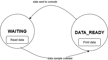
In this exercise you need to implement the state machine depicted in the diagram below.
Every time a new measurement is acquired from the sensor in
sensor_task, change the program state to DATA_READY and transfer the measured value to print_task through the provided global variable. print_task should print the value to the terminal, so remove the printing from sensor_task.Add the missing states to the
state enumeration. A global state variable and a variable for storing the measurement value are already provided in the code.In this task, it could be beneficial to decrease the delay period of
print_task, for example to 500 milliseconds.When you finish this task you have completed the exercise. If you want you can continue with the voluntary task, that will help to integrate the usb-serial-debug library in your code.
Submit both
main.c and sdk.c in the return box below. If necessary, compress them into a .zip file first.Exercise 4 - Using usb-serial-debug (VOLUNTARY)
This task is not mandatory
In this task, use the
usb-serial-debug library together with TinyUSB to send debug messages and application data through two USB CDC interfaces. The print_task sends debug output through CDC0 and sample data through CDC1, following the hello_dual_cdc example that you tested in Session 1.The
print_task:- Use the
usb_serial_printfunction to print the textLux:xxxfor each sample taken, where xxx represents the illuminance value. This debug output is sent through CDC0. - Use the TinyUSB
tud_cdc_n_writefunction to send each sample through CDC1 on a new line in CSV format:timestamp,illuminance. Calltud_cdc_n_write_flushafterwards so that the buffered data is transmitted promptly instead of waiting for the transmit buffer to fill.
You also need to initialize TinyUSB and the
usb-serial-debug library in main. Use the hello_dual_cdc example as a reference. In particular:- Create the USB task that continuously calls
tud_task(). - Initialize TinyUSB with
tusb_init()and the debug serial interface withusb_serial_init()immediately before callingvTaskStartScheduler(). Do not add a delay between this initialization and starting the scheduler. - In
CMakeLists.txt, setpico_enable_stdio_usbto 0, because the application uses its own TinyUSB configuration. - Add
usb_serial_debugto the libraries linked intarget_link_libraries.
To conclude
Now we can control an LED on the JTKJ HAT, read sensor data, and communicate with the outside world using serial communication!