Tilakoneet
Osaamistavoitteet: Opiskelija ymmärtää miten tilakoneita voidaan käyttää sulautetun ohjelman suunnittelussa ja toteutuksessa.
Tilakoneita (engl. finite-state machine, FSM) käytetään yleisesti digitaalitekniikassa sekvenssilogiikan toteuttamiseen. Tämä lisäksi tilakoneita käytetään monipuolisesti tietojenkäsittelytieteessä mallintamisen työkaluna. Sulautetuissa järjestelmissä tilakone on oiva keino mallintaa ohjelmiston toimintaa jo suunnitteluvaiheessa sekä ohjata ja hallita tapahtumapohjaisen ohjelman toimintalogiikaa. Kurssilla tilakoneista on erityisesti hyötyä kun toteutamme tapahtumiin reagointia SensorTagin RTOS:n useiden eri taskien kesken.
Tässä materiaalissa emme mene tilakoneiden salaisuuksiin (formaleihin esityksiin ym.) sen syvemmälle, vaan esitämme miten ne on helppo ottaa osaksi ohjelmamme suunnittelua ja toteutusta. Ohjelmoinnin ammattilaisilla on käytössä ohjelmointiympäristöjä ja työkaluja, joilla esimerkiksi laatia tilakoneita osaksi ohjelmakoodia. Jotkut työkalut jopa automatisoivat itse ohjelmointia tuottamalla valmista koodia tilakonekuvauksesta.
Tilakone
Tilakone on järjestelmän tai prosessin malli, jonka toiminnallisuus kuvataan tiloina ja niiden muutoksina. Esimerkiksi Mealy-tyyppinen tilakone muuttaa tilaansa seuraavasti: tilasiirtymä riippuu nykyisestä tilasta ja tuloista (ts. inputeista). Tilasiirtymien aikana voidaan myös suorittaa toimintoja, jotka tuottavat outputin. Tässä tilakone on deterministinen, eli yhdestä tilasta yhdellä inputilla tuloksena voi olla vain yksi tilasiirtymä. Tilasiirtymäkaavio kuvaa järjestelmän mahdolliset tilat, siirtymät niiden välillä sekä tapahtumat, jotka aiheuttavat siirtymän tilasta toiseen.
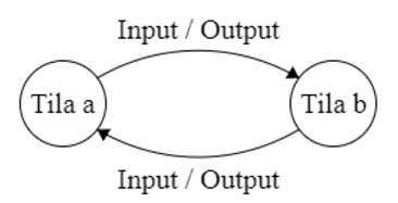
Kuvassa alla tilakoneessa on kaksi tilaa
Tila a ja Tila b. Nuolilla kuvattuihin tilasiirtymiin on liitetty myös niiden inputit ja mahdolliset outputit. 
Tämä yksinkertaistettu tilakoneen esitys riittää meille tällä kurssilla.
Esimerkki tilakoneesta
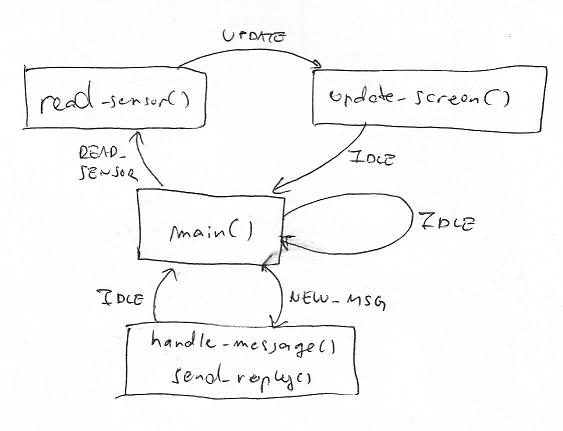
Alla sulautetun ohjelman toiminta kuvattuna tilakoneena. Tilakoneeseen on määritelty toiminnallisuudet, siirtymät ja globaali tilamuuttuja, jonka arvo (=tila) muuttuu tapahtumien seurauksena. Ohjelman toimintalogiikka perustuu tilamuuttujaan niin, että suoritus etenee tapahtumien tilasiirtymien kautta vaiheesta toiseen.
- Tilassa IDLE vain odotetaan tapahtumia ikuisessa silmukassa.
- Kerran sekunnissa saadaan tapahtuma (=ajastinkeskeytys), joka aiheuttaa tilasiirtymän tilasta IDLE tilaan READ_SENSOR.
- Tilasta READ_SENSOR, jossa luetaan uusi anturidata, siirtymä tilaan UPDATE, jossa päivitetään anturidata näkyville laitteen ruudulle.
- Tilasta UPDATE siirtymä takaisin odotustilaan IDLE.
- Ikuisessa silmukassa tarkistetaan onko laitteelle tullut viestejä (tapahtuma). Jos on, tilasiirtymä tilaan NEW_MSG.
- Tilassa käsitellään vastaanotettu viesti
handle_msgja lähetetään vastaussend_reply. - Jonka jälkeen odotuspalataan tilaan IDLE.

Toteutus C-kielellä
Tilakoneen ohjelmoinnissa on neljä periaatetta:
- Tilan toiminnallisuus funktioihin.
- Tilamuutokset sijoitusoperaatioilla tilamuuttujaan. Tästä syystä tilamuuttuja on globaali muuttuja, jotta sen arvoa voidaan käsitellä kaikkialla ohjelmassa!
- Ohjelman ikuisessa silmukassa tarkistetaan tilamuuttujan arvo ja suoritetaan sen mukainen tilasiirtymä.
- Ohjelmassa voi olla useita sisäkkäisiä tilakoneita. Esimerkiksi RTOS:n taskin suorituksessa voi olla oma tilakone, samalla kun koko järjestelmää pyörittää toinen tilakone.
Näiden periaatteiden pohjalta, katsotaanpa eräs tapahtumapohjainen toteutus yo. tilakoneelle SensorTagin taski-ajatteluun pohjautuen.
// Hox! Ao. esimerkki ei toimi suoraan koska IDLE on varattu sana..
// Käytä siis tälle tilalle jotain muuta nimeä.

// Tilaesittelyt
enum state { IDLE=1, READ_SENSOR, UPDATE, NEW_MSG };

// Globaali tilamuuttuja, alustetaan odotustilaan
enum state myState = IDLE;

// Ajastinkeskeytys kerran sekunnissa
Void clkFxn(UArg arg0) {

    // Muutetaan tilaa halutuksi
    // Hox! If-lauseella tarkistetaan, että tilasiirto on mahdollinen!!
    // Nyt sallitaan vain tilasiirtymä IDLE -> READ_SENSOR
    if (myState == IDLE) {

        // Tilasiirtymä IDLE -> READ_SENSOR
        myState = READ_SENSOR;
    }
}

// Tiedonsiirtotaski
Void commTask(UArg arg0, UArg arg1) {

    while (1) {
        // Funktiolla is_message_waiting tarkistetaan
        // onko puskurissa viestejä
        // Lisäksi sallitaan vain tilasiirtymä IDLE -> NEW_MSG
        if (is_message_waiting() == TRUE && myState == IDLE) {

            // Tilasiirtymä IDLE -> NEW_MSG
            myState = NEW_MSG;

            // Tilan toiminnallisuus
            handle_message();
            send_reply();

            // Tilasiirtymä NEW_MSG -> IDLE
            myState = IDLE;
        }
    }
}

// Anturien käsittely
Void sensorTask(UArg arg0, UArg arg1) {

    while (1) {

        if (myState == READ_SENSOR) {

            // Tilan toiminnallisuus
            read_sensor_values();

            // Tilasiirtymä READ_SENSOR -> UPDATE
            myState = UPDATE;
        }

        Task_sleep(..);
    }
}

// Anturien käsittely
Void displayTask(UArg arg0, UArg arg1) {

    while (1) {

        if (myState == UPDATE) {

            // Tilan toiminnallisuus
            update_screen();

            // Tilasiirtymä UPDATE -> IDLE
            myState = IDLE;
        }

        Task_sleep(..);
    }
}
Hox! Ylläoleva tilakonetoteutus ei toimi (ihan tarkoituksella) ilman muokkausta kurssin SensorTag-laitteessa!!
Ohjelmassa on asetettu ajastinkeskeytys kerran sekunnissa, jonka käsittelijä on
clkFxn, joka muuttaa tilan READ_SENSOR-tilaan. Näin tilakoneen avulla luemme sensorin arvon kerran sekunnissa. Samoiten commTask-tehtävässä muutamme tilan NEW_MSG, jos puskurissa on odottamassa viestejä. Huomatkaa oleellinen asia. Nyt
if-lauseella tarkistamme onko tilamuutos luvallinen. Ilman tarkastuksia saattaisi koodissa tulla tilasiirtymiä, jotka eivät ole tarkoituksenmukaisia ja sotkevat ohjelman toiminnan. Yleisesti tilasiirymän luvallisuuden tarkistus on oleellinen osa niiden käyttöä ohjelmissa!!Tilakonetta suunnitellessa tilat kannattaa järjestää esim. kasvavassa numerojärjestyksessä niin, että tilasiirtymien tarkistus voidaan tehdä myös vertailu-operaattorilla (pienempi kuin, jne) suorivaaivaisesti. Tietysti tässä kannattaa välttää monimutkaisia
if-else-rakenteita! Toinen oleellinen asia koodin rakenteen parantamiseksi on tilojen määrän minimointi. Mutta siihen emme mene tarkemmin tällä kurssilla, muuten kuin että mietimme onko jokin nyt varmasti tarpeen ohjelmassamme. Esimerkissä UPDATE-tila ei ole välttämätön, mutta se tarvitaan, koska teemme ruudun päivityksen omassa taskissaan. Näin tilamuuttujan avulla hallitsemme ohjelman toimintalogiikkaa eri taskien välillä!Toinen käyttötapaus tilakoneelle sulautetuissa ohjelmissa on käyttöliitttymän toimintalogiikan toteuttaminen. Tilakoneen avulla voimme määritellä (rajatulle resurssille) kuten SensorTagin kahdelle painonapille ohjelman tilasta riippuvaa erilaista toiminnallisuutta. Esimerkiksi MENU-tilassa yksi nappi on omistettu virtanapiksi, mutta PELI-tilassa sitä voidaan käyttää johonkin muuhun. Kätevää!
Lopuksi
Tilakoneita tullaan käyttämään kurssin harjoitustyössä.
Anna palautetta
Kommentteja materiaalista?