Sarjaliikenne
Osaamistavoitteet: Kaksi tapaa sarjaliikenteen toteutukseen sulautetussa laitteessa.
Sarjaliikenne tarkoittaa laitteiden tai komponenttien keskinäisessä tiedonsiirrossa käytettäviä tekniikoita, joissa data siirtyy sarjamuodossa eli peräkkäin bitti kerrallaan yhtä linjaa pitkin. Data voi siirtyä yhtä linjaa yhteen suuntaan, jolloin lähetykseen ja vastaanottoon on omat linjansa, tai synkronoidusti voidaan käyttää samaa linjaa vuorotellen lähetykseen ja vastaanottoon. Jälkimmäisessä tapauksessa viestintä synkronoidaan usein kellolinjalla (synkroninen viestintä). Ensimmäisessä tapauksessa, kun käytössä on vain kaksi viestintälinjaa, kellosignaalia ei yleensä ole ja viestintä on asynkronista.
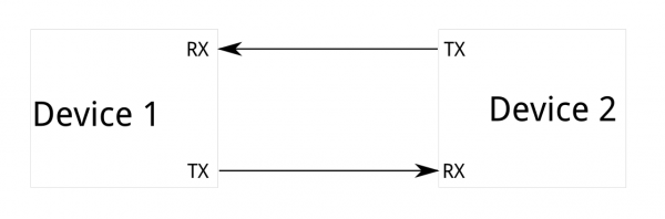
Kuvassa yksinkertaistettuna sarjaliikenteen idea. Kaksi laitetta on määritellyt itselleen I/O-pinneistä lähetys- (Tx-pinni) ja vastaanotto-linjat (Rx-pinni). Laitteet kytketään toisiinsa siten, että toisen lähetys on toisen vastaanotto. Näin lähettäjän bittijono (Tx-pinnin tilat ajan funktiona) näkyvät vastaanottajan Rx-pinnin tiloissa.
Tieto siirretään datalinjoja pitkin laitteelta toiselle bittijonona. Tämä tarkoittaa, että siirron molempien osapuolten täytyy olla yhtä mieltä viestin rakenteesta (kunkin bitin merkityksestä), eli datan siirtoprotokollasta.
Lisäksi molempien täytyy käyttää samaa siirtonopeutta.
Lisäksi molempien täytyy käyttää samaa siirtonopeutta.
Tiedonsiirtoprotokollan viestikehyksen sisällä siirrämme varsinaisen informaation, mutta lisäksi protokollassa voi olla esimerkiksi virheenkorjaukseen liittyvää tietoa lisänä.
Sarjaliikenneprotokollat ovat yleensä standardoituja, joka auttaa (eri valmistajien) erilaisia laitteita kommunikoimaan keskenään. Siirtonopeus taas määrittää sen mikä on bitin ajallinen kesto linjassa. Jos tätä ei tiedetä, on vastaanottopään vaikea osata tulkita bitit oikein jonosta, eli se ei tiedä missä kohti signaalia bitti alkaa ja päättyy ja missä kohti signaalia bitin arvo luetaan. Siirtonopeuden voi myös määrittää ym. kello.
Aiemmin esitelty vaihtoehto komponenttien (ja järjestelmien) väliselle tiedonsiirrolle on rinnakkainen tiedonsiirto, eli tyyppiesimerkkinä juurikin tietokoneen osoite-, ohjaus- ja dataväylät, joissa bitit siirtyvät yhtaikaa samanaikaisesti omia johtimiaan pitkin. Rinnakkainen tiedonsiirto on siis nopeampaa kuin sarjamuotoinen, mutta hintana on lisätarve rinnakkaisille johtimille ja I/O-pinneille. Tässä mielessä sarjaliikenne on taloudellisempaa ja siirtonopeudetkin ovat nykyään kovasti kehittyneet.
Tällä kurssilla emme perehdy sarjaliikenteen salaisuuksiin sen syvemmin. Erilaisia enemmän tai vähemmän standardoituja toteutuksia onkin paljon, joista esittelemme (ja käytämme) Picoon toteutetun yleisen sarjaliikennetoteutuksen UART:n ja laajennusalustan anturien kanssa käytettävän i2c-protokollan. i2c on todella yleinen ja varsin nopea (kellotaajuus 100-400kHz) sarjaliikenneprotokolla sulautettuihin järjestelmiin.
Universal Asynchronous Receiver/Transmitter
Universal Asynchronous Receiver/Transmitter (UART), on sarjaliikennepiiri, joka muuntaa rinnakkaismuotoista tietoa sarjamuotoiseksi kommunikaatioon oheislaitteen kanssa. Piirin avulla voimme toteuttaa esim. tunnetun RS-232 standardin mukaista tiedonsiirtoa. UART on yleiskäyttöinen ja hieman vanhahko tekniikka, mutta sulautetuissa järjestelmissä yleisesti käytössä ASCII/tekstimuotoiseen kommunikointiin kaksisuuntaisesti. UART:ia voidaan käyttää myös binäärimuotoisen ("numeroiksi koodatun") datan siirtämiseen, josta esimerkkinä sulautetun laitteen ohjelmamuistiin kirjoittaminen, kun päivitämme ohjelmamme laitteelle.
Tyyppiesimerkki sulautetuissa järjestelmissä UARTia käyttävästä oheislaitteesta on GPS-vastaanotin, joka lähettää koordinaattitietoa ihmisen luettavassa NMEA-tekstimuodossa. Toinen esimerkki voisi olla ohjelmoijan toteuttama pienehkö komentotulkki UART-pohjaisena sarjaliikenteenä työasema-PC:n ja sulautetun laitteen välillä. Ja tietysti CSV-muotoista informaatiota voi siirtää UART:n avulla..
Menemättä liialti protokollan toteutukseen, todetaan että UART-pohjaiselle sarjaliikenteelle tulee asettaa muutama tiedonsiirtoparametri:
- Siirtonopeus (baudia). Tyypillisiä nopeuksia ovat 9600, 19200, 38400, 57600 ja 115200 bittiä/sekunti.
- Databittien määrä: kurssilla aina 8.
- Pariteettibitti: kurssilla ei käytetä.
- Stop-bittien määrä: kurssilla aina 1.
Tällöin sarjaliikenteen parametreistä käytetään lyhennettä (esim) 9600 8n1. Oleellista on tietysti konfiguroida sekä lähetyspää että vastaanottopää samoilla parametreillä, jotta ne ymmärtävät toisiaan. Etuna tässä on, että kun parametrit tiedetään, niin kellolinjalle ei ole tarvetta.
Pico UART
Seuraavaksi käymme läpi esimerkin avulla, miten Pico SDK:n sarjaliikenteen
uart-kirjastoa käytetään. Tässä ao.
serialTask-tehtävässä siis:- Ensin alustetaan sarjaliikenne
uart0:lle parametreillä (9600, 8N1). - Sen jälkeen konfiguroidaan GPIO-pinnit 0 ja 1 toimimaan UART-pinneinä
gpio_set_function-funktiolla. Näin asetetaan fyysiset TX- ja RX-linjat. - Ikuisessa silmukassa odotetaan
uart_getc-funktiolla, kunnes sarjaliikenteen kautta laitteelle lähetetään merkki. - Huomaa, että jos haluat lukea useamman merkin kerralla, voit käyttää funktiota
uart_read_blocking(uart0, buffer, buffer_len), jossa buffer on määritelty muodossauint8_t buffer[buffer_len]. - Kun merkki on saapunut, käytetään
sprintf-funktiota merkkijonon muotoiluun (esimerkiksi: "Received: A") ja lähetetään se takaisinuart_puts-funktiolla. Parametreinä siis käytettävä UART-väylä ja lähetettävä merkkijono. - Huomaa myös, että jos haluat lähettää useamman merkin kerralla, voit käyttää funktiota
uart_write_blocking(uart0, buffer, buffer_len), jossa buffer on määritelty muodossauint8_t buffer[buffer_len]. - Lopuksi kutsutaan
vTaskDelay, joka keskeyttää tehtävän 100 ms ajaksi ja antaa aikaa muille tehtäville ennen kuin silmukka alkaa alusta.
HOX!!: On tarpeen tarkistaa, kumpi kahdesta käytettävissä olevasta UARTista (UART0 tai UART1) voidaan kytkeä mihinkin pinniin. Tämä löytyy esimerkiksi Picon pinout-kaaviosta.
#include <hardware/uart>
...
// Taskifunktio
void serialTask(void *pvParams) {

    char input;
    char echo_msg[30];

    // Alustetaan sarjaliikenne
    // Parametrit 8n1 9600
    uart_init(uart0, 9600);
    // Asetetaan UART käyttämään oletuspinnejään
    gpio_set_function(0, GPIO_FUNC_UART);
    gpio_set_function(1, GPIO_FUNC_UART);

    // Ikuinen elämä
    while(1) {
        // Vastaanotetaan 1 merkki kerrallaan input-muuttujaan
        input = uart_getc(uart0);
        // Lähetetään merkkijono takaisin
        sprintf(echo_msg, "Received: %c\n", input);
        uart_puts(uart0, echo_msg);
        // Kohteliaasti nukkumaan sekunniksi
        vTaskDelay(100 / portTICK_PERIOD_MS);
    }
}

int main(void) {
    ...
    stdio_init_all();
    ...
    return 0;
}
Sarjaliikenne UART:n kautta Picolla on siis yksinkertaista luku- ja kirjoitusfunktioiden käyttämistä, kunhan sarjaliikenneyhteys on ensin avattu. Yhteyttä avatessa on myös muistettava asettaa halutut pinnit UART:in käyttöön
gpio_set_function-kutsulla.Lopuksi sarjaliikenneyhteys pitää sulkea
uart_deinit-kutsulla, mutta esimerkissä sitä ei ole, koska toimimme ikuisessa silmukassa.Sarjaliikennekeskeytys
Viime esimerkillä kävimme läpi tavan lukea sarjaporttidataa
uart_getc-funktiolla niin, että taski jäi jumiin odottamaan dataa saapuvaksi (engl. blocking). Tämä ei kuitenkaan ole paras tapa odottaa dataa UART, koska ..no taski jäi jumiin. Nyt MCU:n näkökulmasta sarjaliikenne UART:n kautta on hidas operaatio, joten tämä ei ole hyvä tapa. Parempi tapa on asettaa sarjaliikenne toimimaan ei-blokkaavasti niin että vasta kun uutta dataa on tarjolla, keskeytys tapahtuu. Tämä hoituu UART:n asetusparametrejä muuttamalla ja tietysti laatimalla käsittelijä.
// Käsittelijäfunktio
void uartFxn() {
    // Nyt dataa on saatavilla, se annetaan toisen funktion käsiteltäväksi (esimerkin vuoksi)
    tehdaan_jotain_nopeasti(uart_getc(uart0));

}

void uartTask(void *pvParams) {

    uart_init(uart0, 9600);

    gpio_set_function(0, GPIO_FUNC_UART);
    gpio_set_function(1, GPIO_FUNC_UART);

    // Asetetaan keskeytyksen käsittelijä uartFxn UART0:n keskeytyksille
    irq_set_exclusive_handler(UART0_IRQ, uartFxn);
    // Aletaan vastaanottamaan keskeytyksiä
    irq_set_enabled(UART0_IRQ, true);

    // Kerrotaan UART:ille, että haluamme ottaa vastaan keskeytyksiä,
    // kun dataa on luettavissa.
    uart_set_irq_enables(uart0, true, false);

    while(1) {
        // Ikuinen looppi
        tight_loop_contents();
    }

}

int main(void) {
    ...
    stdio_init_all();
    ...
    return 0;
}
Nyt koodissa alustetaan Pico SDK:n
uart-kirjasto taskin sisällä, eikä main-funktiossa. Ajatuksena edelleenkin se, että eriytämme sarjaliikenteen omaan taskiinsa.Erona aiempaan sarjaliikenteen alustukseen on keskeytyksenkäsittelijän asettaminen funktiolla
irq_set_exclusive_handler, sekä keskeytysten käyttöönotto funktioilla irq_set_enabled ja uart_set_irq_enables. Näillä funktioilla kerromme ensin prosessorille, että haluamme käsitellä UART-keskeytyksiä (vakio UART_IRQ). Tämän jälkeen konfiguroidaan itse UART-laite generoimaan keskeytyksiä kutsumalla uart_set_irq_enables. Kun tämän funktion toinen argumentti asetetaan arvoon
true, otetaan käyttöön vastaanottokeskeytykset eli saamme keskeytyksen aina kun dataa saapuu UART:iin. Voisimme myös ottaa käyttöön keskeytykset lähetystä varten (kolmas argumentti), mutta tässä esimerkissä sitä ei tarvita. UART ja USB
Perinteinen tapa kommunikoida tietokoneen kanssa on ollut UART-rajapinnan kautta. Koska nykyaikaisissa tietokoneissa ei enää ole fyysisiä sarjaportteja, tarvitaan erillinen sovitin, joka muuntaa UART-signaalit (TTL-tasot) USB:ksi. Tämä tehdään FTDI-sovittimella (tunnetaan myös nimellä TTL-to-Serial), joka voi olla yksinkertainen kaapeli tai kehitysalustalle integroitu piiri. Esimerkiksi monet Arduino-kehitysalustat ja TI SensorTag sisältävät tällaisen piirin ilman, että käyttäjän tarvitsee edes huomata sitä — näin USB-kaapelin kautta tapahtuva yhteys muunnetaan taustalla UART-kanavaksi. Kun kommunikoimme työaseman kanssa, sen sarjaportille (/dev/ttyACM0, in Unix, COMx in Windows, jne) pitää tietenkin asettaa vastaavat nopeus ja asetukset. Picon ajurit luovat työasemissa USB-liitynnästä yhden loogisen sarjaportin (nimeltään Raspberry Pi Pico), jota voidaan käyttää esim. terminaaliohjelman, screen tai Putty avulla kommunikointiin laitteen kanssa.
Sen sijaan Raspberry Pi Pico voi toimia suoraan USB-laitteena ilman mitään ulkoista sovitinta. Se tukee USB-luokkaa CDC-ACM, mikä tarkoittaa, että se voi esittäytyä isäntäkoneelle 'virtuaalisena COM-porttina''. Tällä tavalla, kun kutsumme esimerkiksi
printf-funktiota koodissamme, teksti voidaan lähettää USB:n kautta ja se näkyy ikään kuin se olisi välitetty UARTin kautta. Näin Pico mahdollistaa sarjaviestinnän suoraan USB:n yli, mutta antaa silti mahdollisuuden käyttää fyysisiä UART-pinnejä, jos haluamme oikean laitteistotason sarjayhteyden toiseen laitteeseen. Koska kyseessä on sarjaviestintä, voimme käyttää Picoon kommunikointiin mitä tahansa aiemmin mainituista ohjelmista, esimerkiksi screen tai Putty. Lisää USB-viestinnästä alempana.
I2C-väylä
i2c-sarjaliikenneväylä on hyvin tunnettu binäärimuotoinen sarjaliikenneprotokolla sulautettuihin laitteisiin.
I2C-väylän toiminta perustuu master/slave-arkkitehtuuriin, jota on käytetty tietotekniikassa sen alkuajoista lähtien. Väylään on aina liitetty yksi master-laite, joka ohjaa väylää, sekä n slave-laitetta. Master aloittaa yhteyden ja määrittelee siirtonopeuden, jota slave-laitteet seuraavat. I2C tarvitsee kaksi I/O-pinniä: kellosignaalin (Serial Clock Line, SCL) ja datalinjan (Serial DAta Line, SDA).
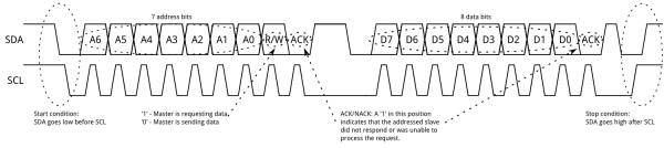
I2C-väylällä laitteet ja komponentit tunnistetaan osoitteilla. Osoite on laitteen valmistajan ennalta määrittelemä, ja se löytyy komponentin datalehdestä. Joskus valmistaja tarjoaa komponentille useita I2C-osoitteita, jolloin käyttäjä voi valita sopivan osoitteen. Tämä on erittäin hyödyllistä etenkin silloin, kun samassa väylässä on useita samanlaisia komponentteja, esimerkiksi antureita. Yhdessä I2C-väylässä voi olla jopa 1008 laitetta yhtä aikaa! I2C-laitteen osoite on 7 bittiä, ja sitä seuraa yksi bitti, joka ilmaisee onko toiminto luku (1) vai kirjoitus (0).
Yleisesti ottaen I2C-viestit koostuvat kahdesta pääelementistä: vastaanottajan osoitteesta ja viestirungosta. Vastaanottajan osoite on tavallisesti yhden tavun mittainen (7 osoitebittiä + r/w-bitti), ja se määrittelee, minkä laitteen tulee vastata. Viestirunko voi sisältää komennon ja mahdollisesti myös dataa. Jokainen transaktio alkaa START-ehdolla. Esimerkiksi I2C-LCD-moduulilla master voi kirjoittaa komennon kursorin siirtämiseksi, sitten lähettää datatavuja merkkien näyttämiseksi, ja jos moduuli tarjoaa luettavia tilarekistereitä, lukea takaisin tietoja kuten varattuna/valmiina -lipun tai näppäimistön tilan ennen seuraavaa komentoa. Jokainen transaktio, joka voi sisältää useita tavuja, päätetään STOP-ehdolla.
Sulautetuissa järjestelmissä, erityisesti digitaalisia antureita käytettäessä, tämä ajatus tarkentuu rekistereihin. Yleisten komentojen sijaan master määrittelee rekisteriosoitteen anturista, johon se haluaa päästä käsiksi. Sen jälkeen master joko kirjoittaa dataa kyseiseen rekisteriin (konfigurointi) tai lukee siitä dataa (mittaustulos).
Kirjoitustransaktio (rekisterin arvon muuttaminen) on yksinkertainen: ensimmäinen tavu transaktiossa (START-ehdon jälkeen) on rekisterin numero, ja sitä seuraavat tavut (STOP-ehdon asti) sisältävät rekisteriin kirjoitettavan datan.
Lukutransaktio on hieman monimutkaisempi. Ensin master kirjoittaa sen rekisterin osoitteen, jota se haluaa lukea. Sen jälkeen se lähettää repeated START -ehdon (saman transaktion sisällä) ja aloittaa lukuoperaation, johon sisältyy laitteen osoitteen lähettäminen uudelleen luku-bitin ollessa asetettuna.
Alla esimerkki i2c-viestien kehysrakenteesta. Tämä vain tiedoksi.
i2c Picossa
Seuraavaksi katsotaanpa Pico SDK:n tarjoaman
i2c-kirjaston käyttöä koodiesimerkin avulla. Esimerkissä luemme Picon laajennusalustalla olevalta lämpötila-anturilta HDC2021 lämpötilan. Kuten huomaamme, on anturin datakirja täynnä monenlaista vaikeaselkoista informaatiota, johon kurssilla ei tarvitse perehtyä. Kurssilla meitä kuitenkin kiinnostaisi anturin rekisterien käyttö (kappale 7.6 datakirjassa) i2c-väylän avulla. Mutta teemme sen nyt alla perustuen valmiisiin vakioihin. // i2c-kirjasto mukaan ohjelmaan
#include <hardware/i2c.h>
...
// Taskifunktio
void sensorTask(void *pvParameters) {
float temperature;
// Alustetaan I2C-väylä
i2c_init(i2c_default, 400*1000);
// Asetetaan Picon oletuspinnit I2C:lle ohjelman käyttöön
    gpio_set_function(PICO_DEFAULT_I2C_SCL_PIN, GPIO_FUNC_I2C);
    gpio_set_function(PICO_DEFAULT_I2C_SDA_PIN, GPIO_FUNC_I2C);
    gpio_pull_up(PICO_DEFAULT_I2C_SCL_PIN);
    gpio_pull_up(PICO_DEFAULT_I2C_SDA_PIN);
// i2c-viesteille lähetys- ja vastaanottopuskurit
uint8_t txBuffer[1]; // Nyt lähetetään yksi tavu
uint8_t rxBuffer[2]; // Nyt vastaanotetaan kaksi tavua
txBuffer [0] = HDC2021_TEMP_LOW;
while(1) {
if(i2c_write_blocking(i2c_default, HDC2021_I2C_ADDRESS, txBuffer, 1, true) != PICO_ERROR_GENERIC) {
if(i2c_read_blocking(i2c_default, HDC2021_I2C_ADDRESS, rxBuffer, 2, false) != PICO_ERROR_GENERIC) {
// Muunnetaan 2-tavuinen data rxBuffer:ssa
// lämpötilaksi (kaava harjoitustehtävissä)
//PART OF THE LAB SESSION
temperature = ... ;
// Temperature value to console window
printf("%f", temperature);
}
else {
printf("I2C Bus fault\n");
}
}
else {
printf("I2C Bus fault\n");
}
vTaskDelay(1000 / portTICK_PERIOD_MS);
}
// i2c-yhteyden sulkeminen, tosin ikuinen silmukka ei koskaan päädy tänne
i2c_deinit(i2c_default);
}
int main() {
...
stdio_init_all();
...
return 0;
}
Puretaanpas esimerkki.
Alustukset ja käyttöönotto
Samoin kuten muidenkin oheiskomponenttien kanssa, Pico SDK tarjoaa meille joukon funktioita ja vakioita niiden alustukseen ja käyttämiseen. Huomataan, että esimerkissä kaikki i2c:hen liittyvät toiminnot tehdään
sensorTask:in sisällä. Ideana on siis että tämä taski hoitaa kaiken i2c-liikenteen sensorien kanssa.Nyt i2c otetaan käyttöön Picon
i2c-kirjaston tarjoamalla alustusfunktiolla, jolle meidän pitää kertoa, kumpaa Picon i2c-väylistä haluamme käyttää. Tässä valitsemme siis oletusväylän i2c_default. Alustusfunktio haluaa myös tietää nopeuden, jolla tietoa siirretään väylässä, nyt asetamme sen arvoon 400 kHz. i2c_init(i2c_default, 400*1000);
Aivan kuten UART:in kanssa, meidän tulee varata pinnejä i2c:n käyttöön. Tässä käytämme myös Picon oletuspinnejä, ja asetamme niiden toiminnallisuudeksi i2c-liikenteen. Lisäksi asetamme pinnit tiedettyyn tilaan, joka on tässä
high funktiolla gpio_pull_up gpio_set_function(PICO_DEFAULT_I2C_SCL_PIN, GPIO_FUNC_I2C);
gpio_set_function(PICO_DEFAULT_I2C_SDA_PIN, GPIO_FUNC_I2C);
gpio_pull_up(PICO_DEFAULT_I2C_SCL_PIN);
gpio_pull_up(PICO_DEFAULT_I2C_SDA_PIN);
Kommunikointi i2c-väylällä
Esimerkissä kysymme siis lämpötila-anturilta HDC2021 mittausarvoja. Tätä varten meidän on määritettävä tiedolle säilytyspaikat, joita myös puskureiksi (engl. buffer) kutsutaan. Määritämme kaksi puskuria:
- Lähetyspuskuri
txBuffer, jonka koko kerrotaan datakirjassa (ok, meillä kurssimateriaalissa). Tyypillisesti lukuoperaatiossa tarvitsee lähettää ainoastaan sen rekisterin osoite, jonka arvon haluamme lukea. - Esimerkissä asetamme HDC2021-anturin datarekisterin osoitteen lähetyspuskuriin
txBuffer[0] = HDC2021_TEMP_LOW;käyttäen kirjastossa annettua vakiota. - Vastaanottopuskuri
rxBuffer, jonne vastaanotettu i2c-viesti tallennetaan. Vastaavasti puskurin koko kerrotaan datakirjassa. - Kurssimateriaalista tiedämme, HDC2021-anturi palauttaa lämpötilan arvon 16-bittisenä lukuna, joten vastaanottopuskurin koko on kaksi tavua.
    uint8_t txBuffer[1];
    uint8_t rxBuffer[2];

    txBuffer[0] = HDC2021_TEMP_LOW;
Hox! On myös mahdollista lähettää i2c-viestejä, jotka eivät vastaanota mitään dataa, kuten jotkut komennot. Tällöin emme luonnollisesti tarvitse puskuria datan lukemiseen.
Kun puskurit on määritetty ja lähetyspuskuriin on sijoitettu luettavan rekisterin arvo, voimme lähettää viestin oheislaitteelle.
Huomaa, että transaktiota ei päätetä tässä vaiheessa, koska parametrin 'noStop' arvo on
Huomaa, että transaktiota ei päätetä tässä vaiheessa, koska parametrin 'noStop' arvo on
true funktiokutsussa i2c_write_blocking. Mikäli tapahtuu virhe, palautuu i2c_write_blocking-funktiokutsun tuloksena vakio PICO_ERROR_GENERIC. Tällöin tiedämme, että viestin lähetyksessä tapahtui virhe, eikä meidän kannata yrittää lukea arvoa. if(i2c_write_blocking(i2c_default, HDC2021_I2C_ADDRESS, txBuffer, 1, true) != PICO_ERROR_GENERIC) {
...
}
else {
printf("I2C Bus fault\n");
}
Mikäli virhettä taas ei tapahdu, voimme lukea anturin antaman arvon:
...
    if(i2c_read_blocking(i2c_default, HDC2021_I2C_ADDRESS, rxBuffer, 2, false) != PICO_ERROR_GENERIC) {
    temperature = ... ;
    printf("%f", temperature);
    }
    else {
    printf("I2C Bus fault\n");
    }
...
Tässäkin huomioimme mahdollisen i2c-väylän virhetilanteen, ja ilmoitamme siitä konsoli-ikkunaan.
Jos viestin lukeminen kuitenkin onnistuu, anturin datarekisterin 16-bittinen arvo on nyt tallentunut vastaanottopuskurin
rxBuffer kahteen tavuun. Ohjelmoijan tehtäväksi jää muuntaa rxBuffer:n arvo lämpötilaksi. Kaava tähän on esitetty harjoitustehtävissä ja myöhemmässä kurssimateriaalissa.i2c-yhteyden sulkeminen
Ohjelmassa voi tulla tarve sulkea i2c-yhteys. Se tapahtuu allaolevan mukaisesti:
   ...
   i2c_deinit(i2c_default);
   ...
USB RP2040:ssa
RP2040:ssa on integroitu USB-ohjain, joten voimme käyttää USB:tä suoraan ilman ulkoisia piirejä.
Tämä ohjain voi toimia kahdessa tilassa: USB-isäntänä (ohjaa muita USB-laitteita kuten näppäimistöä tai muistitikkuja) tai USB-laitteena (näkyy tietokoneelle oheislaitteena).
Meitä kiinnostaa tässä tapauksessa laitteen tila, jossa Pico tukee CDC-ACM-profiilia (Communications Device Class – Abstract Control Model).
Tämän profiilin ansiosta Pico voidaan esittää virtuaalisena sarjaporttina, jolloin sarjaliikenne (yleensä UART TTL -signaalit) voidaan siirtää USB:n kautta.
Tämä on erittäin kätevää, koska sen avulla voimme kommunikoida suoraan tietokoneen tai työaseman kanssa ohjelmilla kuten minicom, screen tai millä tahansa muulla sarjaterminaalilla.
Kulissien takana Pico SDK käyttää TinyUSB-kirjastoa USB-toiminnallisuuden tarjoamiseen.
Seuraavissa esimerkeissä näemme, miten Raspberry Pi Pico voi lähettää dataa tietokoneelle USB:n kautta.
Kun käytät TinyUSB:tä omassa projektissasi, kaksi tiedostoa on oleellista:
Seuraavissa esimerkeissä näemme, miten Raspberry Pi Pico voi lähettää dataa tietokoneelle USB:n kautta.
Kun käytät TinyUSB:tä omassa projektissasi, kaksi tiedostoa on oleellista:
tusb_config.h: konfiguraatioheaderi, jossa määritellään mitkä USB-luokat otetaan käyttöön (esimerkiksi CDC, HID, MSC), puskurikoot sekä muut käännösaikaiset asetukset.usb_descriptors.c: lähdekooditiedosto, joka määrittelee kuvaajat (deskriptorit), joilla Pico esittäytyy isäntäkoneelle (esimerkiksi CDC-ACM-virtuaalisena sarjalaitteena), mukaan lukien vendor/product ID:t ja merkkijonokuvaukset.
Näistä tiedostoista ei tarvitse huolehtia erikseen, sillä esimerkkikonfiguraatiossa olemme jo sisällyttäneet ne valmiiksi.
stdin ja stdout USB:n kautta
Toinen vaihtoehto, usein käytännössä yksinkertaisin, on ohjata C-kieliset virtaukset
stdin, stdout ja stderr Picon USB CDC-ACM -rajapintaan. Kun tämä on asetettu, laite näkyy isäntäkoneessa sarjaporttina; sen voi avata terminaalilla kuten minicom tai PuTTY, ja tämän jälkeen voit lähettää ja vastaanottaa tekstiä tai binääridataa tavallisten I/O-funktioiden kautta.Jotta USB toimisi stdio-taustajärjestelmänä, se täytyy alustaa ohjelmakoodissa ja ottaa käyttöön käännösvaiheessa. Koodissa voit kutsua
stdio_init_all() tuodaksesi käyttöön kaikki sallitut taustajärjestelmät, tai stdio_usb_init() jos haluat alustaa vain USB-taustajärjestelmän. Käännöksessä USB-stdio pitää linkittää ja ottaa käyttöön kohteelle. Pico SDK:ssa tämä tehdään yleensä CMake-määrityksellä:pico_enable_stdio_usb(your_target 1) pico_enable_stdio_uart(your_target 0) // valinnainen
Tämä tuo mukaan vaaditun
pico_stdio_usb-tuen ja ohjaa C-virtaukset USB:lle kyseisessä ohjelmassa. UARTin poistaminen käytöstä on valinnaista, mutta vähentää sekaannusta tulosteen kohteesta.Kun USB-stdio on aktiivinen, voit käyttää tavallisia C:n I/O-funktioita yhdessä muutamien Pico-kohtaisten apujen kanssa. Yksittäisten merkkien tulostamiseen
stdout:iin putchar() kirjoittaa yhden merkin, ja USB-taustajärjestelmässä rivinvaihto \n muunnetaan usein muotoon \r\n, mikä sopii monille terminaaleille. Jos haluat lähettää tavut sellaisenaan (esimerkiksi binääridatan), käytä Pico-apua putchar_raw(), joka ei tee rivinvaihtojen muunnoksia. Kokonaisten tekstirivien tulostamiseen puts() kirjoittaa C-merkkijonon ja lisää rivinvaihdon automaattisesti. Muista, että sama rivinvaihdon muunnos pätee USB:llä, jos et käytä raw-polkua.Suurempaa läpäisykykyä varten kannattaa käyttää lohkotulostusta. Vakiofunktio
fwrite(char *ptr, int size, int count, stdout) lähettää muistista tavulohkon virtaan ja on ihanteellinen, kun käytössä on puskuroidut tiedot kuten sensorikehykset tai ääninäytteet. Suuren fwrite()-kutsun jälkeen voi olla tarpeen tyhjentää puskuri, jotta data lähtee laitteesta nopeasti; tätä varten voi käyttää C-kirjaston fflush(stdout)-funktiota tai Pico-apua stdio_flush().Lukeminen on symmetristä. Vakiofunktio
getchar() suorittaa estävän luvun yhdelle merkille stdin:ista. Tällöin ohjelma odottaa, kunnes jotain saapuu USB-sarjayhteyden kautta. Jos et halua estävää toimintaa, Pico SDK tarjoaa getchar_timeout_us(timeout_us)-funktion. Kun aikaraja on nolla, kutsu muuttuu ei-estäväksi kyselyksi: jos tavu on saatavilla, saat sen epänegatiivisena paluuarvona; jos ei, tuloksena on PICO_ERROR_TIMEOUT. Tämä sopii pääsilmukoihin, joiden täytyy jatkaa muita tehtäviä mutta aika ajoin tarkistaa sisääntuleva data. Jos tarvitset useiden tavujen lukemista kerralla, tavallinen puskuroitu I/O kuten fread() stdin:ista toimii hyvin ja sopii luontevasti yhteen fwrite():n kanssa esimerkiksi kaiku- tai välitystoimintoihin.Tässä on kompakti esimerkki, joka kokoaa asiat yhteen edellä kuvatulla tavalla:
#include <stdio.h>
#include "pico/stdlib.h"
#include "pico/stdio.h"

int main(void) {
    stdio_init_all();                 // tai stdio_usb_init();

    while (!stdio_usb_connected()) {  // valinnainen: odota terminaalia
        sleep_ms(10);
    }

    puts("USB valmis.");

    while(1) {
        int ch = getchar_timeout_us(1000);   // ei-estävä kysely
        if (ch >= 0) {
            putchar_raw((char)ch);           // kaiku: lähetä takaisin tismalleen mitä saatiin
        }
        // Esimerkki lohkotulostuksesta muualla:
        // fwrite(buf, 1, len, stdout);
        // stdio_flush();
        tight_loop_contents();
    }
}
Tällä asetuksella sinulla on selkeät vaihtoehdot:
putchar() ja puts() sopivat ihmisen luettaviin lokitulosteisiin, putchar_raw() ja fwrite() antavat tarkan tavukontrollin ja tehokkaat lohkolähetykset, ja getchar()/getchar_timeout_us() kattavat estävän ja ei-estävän syötteen luvun.Erillinen debuggaus- ja sarjaportti USB:n kautta
Helpottaaksemme elämääsi olemme luoneet kirjaston, joka tuottaa kaksi erillistä sarjaporttia. Toinen on sarjadataa varten käyttäen TinyUSB-kirjastoa ja toinen debug-viestien lähettämiseen. Löydät tämän kirjaston harjoituksissa jaetusta projektista.
Debug-viestien lähettämiseksi ei voida käyttää tavallisia stdio-funktioita (
printf, puts, …), vaan kurssia varten valmisteltua mukautettua kirjastoa. Lisäksi kirjasto integroituu FreeRTOS:iin, joten sinun ei tarvitse huolehtia yhteensopivuusongelmista. Sinun ei myöskään tarvitse kirjoittaa tiedostoja descriptors.c tai tusb_config, sillä ne sisältyvät kirjastoon. Riittää, että linkität kirjaston CMake-projektiisi ja poistat käytöstä pico_enable_stdio_usb(your_app 0), koska emme käytä tavallista stdio-ratkaisua.Tietokoneellasi sinun täytyy luoda sarjaterminaali (esim. *Arduino*, *minicom*, *screen*, *PuTTY*, …). Unix-järjestelmissä alempi portti (
/dev/ttyACM0) toimii kuten printf, kun taas ylempi portti (/dev/ttyACM1) on käytössä datan lähettämiseen ja vastaanottamiseen TinyUSB interface:n kautta.Aloitetaan esimerkillä, joka lähettää sensoridataa Picosta tietokoneellesi. Data käsitellään yhdessä tehtävässä ja lähetetään tietokoneen terminaaliin:
#include "pico/stdio.h"

#include "FreeRTOS.h"
#include "task.h"
#include "tusb.h"

#define CDC_ITF_TX      1


// ---- Tehtävä, joka tuottaa sensoridataa ----
static void sensorTask (void *arg){
    char buf[BUFFER_SIZE];

    while (!tud_mounted() || !tud_cdc_n_connected(1)){
        vTaskDelay(pdMS_TO_TICKS(50));
    }

    while (1) {
        int temp = ....; // Haettu jostain muualta koodista
        int lux  = ....; // Haettu jostain muualta koodista

        if (tud_cdc_n_connected(CDC_ITF_TX)){
            // Lähetä tiedot käyttäen tud_cdc_n_write
            snprintf(buf, BUFFER_SIZE, "%d, %d\n", temp, lux);
            tud_cdc_n_write(CDC_ITF_TX, buf, strlen(buf));
            tud_cdc_n_write_flush(CDC_ITF_TX);
        }
        vTaskDelay(pdMS_TO_TICKS(1000));
    }
}


// ---- Tehtävä, joka pyörittää USB-pinoa ----
static void usbTask(void *arg) {
    (void)arg;
    while (1) {
        tud_task();              // FreeRTOS:issa odottaa tapahtumia
                                 // Älä lisää vTaskDelay.
    }
}


int main (void) {


    // Luo tehtävät
    TaskHandle_t hUsb = NULL;
    xTaskCreate(usbTask, "usb", 1024, NULL, 3, &hUsb);
    xTaskCreate(sensorTask, "app", 1024, NULL, 2, NULL);

    #if (configNUMBER_OF_CORES > 1)
        vTaskCoreAffinitySet(hUsb, 1u << 0);
    #endif
    // AlustaTinyUSB. Must go before vTaskStartScheduler();
    tusb_init();
    vTaskStartScheduler();
}
Aloitetaan tarkistamalla kirjastot:
#include#include #include #include
Uutena mukana on <tusb.h>, joka on kirjasto USB:n yli toimivan sarjaportin luomiseen.
main-funktiomme luo kaksi eri tehtävää. Ensimmäinen vastaa koko USB-pinon hallinnasta (nimekkäästi usbTask). Huomaa, että tällä tehtävällä on korkeampi prioriteetti kuin muilla (tässä tapauksessa 3):xTaskCreate(usbTask, "usb", 1024, NULL, 3, &hUsb);Sen runko on hyvin yksinkertainen: se vain kutsuu
tud_task, joka odottaa USB-pinosta tulevia tapahtumia. Huomaa, ettei vTaskDelay:tä tarvitse lisätä, sillä tud_task() blokkaa kunnes tapahtuma saapuu.sensorTask puolestaan lähettää mitatut lämpötila- ja valaistusarvot tietokoneelle. Ensin tarkistetaan, voidaanko dataa lähettää CDC-portin kautta (tässä tapauksessa tunniste 1) käyttäen tud_cdc_n_connected. Jos kyllä, data kirjoitetaan puskuriin snprintf-funktiolla (tämä funktio osoittautuu hyödylliseksi). Lopuksi data lähetetään tud_cdc_n_write(1, buf, strlen(buf))-kutsulla, ja varmistetaan Pico-laitteesta poistuminen tud_cdc_n_write_flush(1)-funktiolla.Mutta entä jos haluamme lähettää dataa tietokoneelta Picoon? Helppoa: käytä sarjaterminaalia kirjoittamiseen. Kuinka Pico pystyy lukemaan sen? Se käyttää callback-funktiota — tarkemmin
void tud_cdc_rx_cb(uint8_t itf);. Voit katsoa koko callback-rajapinnan sources-tiedostosta. Katsotaan, miten se toteutetaan.// callback, kun CDC-liittymään saapuu dataa
void tud_cdc_rx_cb(uint8_t itf){
// varaa puskuri datalle pinosta
uint8_t buf[CFG_TUD_CDC_RX_BUFSIZE + 1];
// lue saatavilla oleva data
// | TÄRKEÄÄ: tee tämä myös CDC0:lle, muuten
// | tulostus CDC0:een voi pysähtyä (RX-puskuri täyttyy)
// | ennen kuin tätä funktiota kutsutaan uudestaan
uint32_t count = tud_cdc_n_read(itf, buf, sizeof(buf));
// tarkista, tuliko data toisesta CDC-liittymästä
if (itf == 1) {
// Käsittele data täällä (esim. tallenna puskuriin tai lähetä toiselle tehtävälle).
// ...
// Vastataan kohteliaasti OK
tud_cdc_n_write(itf, (uint8_t const *) "OK\n", 3);
tud_cdc_n_write_flush(itf);
}
// Valinnaisesti: jos tarvitset C-merkkijonon, voit päättää sen:
// if (count < sizeof(buf)) buf[count] = '\0';
}
Uusi asia tässä on lukukutsu:
Se lukee dataa USB:stä ja tallentaa
uint32_t count = tud_cdc_n_read(itf, buf, sizeof(buf));Se lukee dataa USB:stä ja tallentaa
buf-puskuriin. Sen jälkeen käsittelet datan haluamallasi tavalla. Tässä esimerkissä lähetämme vain ystävällisen kuittauksen takaisin.Huomioitavaa:
- Luku tulisi tehdä molemmilla liittymillä (myös debug-portilla). Vaikka et käyttäisi dataa, luku estää RX-puskuria täyttymästä ja tulostusten estymistä.
- Funktion nimen täytyy olla täsmälleen
- Tämä callback ei ole keskeytyskäsittelijä, jonka kirjoittaisit itse (keskeytykset hoidetaan pinon sisällä). Silti, pidä tämä kevyt: vältä raskasta käsittelyä ja isoja tulostuksia tässä. Siirrä raskaammat tehtävät muille prosesseille.
- Luku tulisi tehdä molemmilla liittymillä (myös debug-portilla). Vaikka et käyttäisi dataa, luku estää RX-puskuria täyttymästä ja tulostusten estymistä.
- Funktion nimen täytyy olla täsmälleen
tud_cdc_rx_cb. Älä nimeä uudelleen, muuten TinyUSB-pino ei tiedä, mihin funktioon ohjata vastaanotettu data.- Tämä callback ei ole keskeytyskäsittelijä, jonka kirjoittaisit itse (keskeytykset hoidetaan pinon sisällä). Silti, pidä tämä kevyt: vältä raskasta käsittelyä ja isoja tulostuksia tässä. Siirrä raskaammat tehtävät muille prosesseille.
Lopuksi näytetään, kuinka Portti 0 (CDC0) otetaan käyttöön debug-datan lähettämiseen. Muokataan hieman alkuperäistä esimerkkiä.
#include <pico/stdio.h>

#include <FreeRTOS.h>
#include <task.h>
#include <tusb.h>
#include "usbSerialDebug/helper.h"

#define CDC_ITF_TX  1
// #define BUFFER_SIZE  ...  // määrittele sopiva koko, jos ei muualla määritelty

// ---- Tehtävä, joka tuottaa sensoridataa ----
static void sensorTask(void *arg) {
    char buf[BUFFER_SIZE];

    // Odota, kunnes USB on liitetty ja CDC1 yhdistetty (dataportti)
    while (!tud_mounted() || !tud_cdc_n_connected(CDC_ITF_TX)) {
        vTaskDelay(pdMS_TO_TICKS(50));
    }

    while (1) {
        int temp = ....; // Haettu jostain muualta koodista
        int lux  = ....; // Haettu jostain muualta koodista

        // Lähetä sensoridata CDC1:n kautta (tietokone lukee /dev/ttyACM1 Unixissa)
        if (tud_cdc_n_connected(CDC_ITF_TX)) {
            snprintf(buf, BUFFER_SIZE, "%d, %d\n", temp, lux);
            tud_cdc_n_write(CDC_ITF_TX, buf, strlen(buf));
            tud_cdc_n_write_flush(CDC_ITF_TX);
        }

        // Lähetä debug-teksti CDC0:n kautta käyttäen apukirjastoa (tietokone lukee /dev/ttyACM0 Unixissa)
        if (usb_serial_connected()) {
            snprintf(buf, BUFFER_SIZE, "temp:%d, light:%d\n", temp, lux);
            usb_serial_print(buf);
            usb_serial_flush();
        }

        vTaskDelay(pdMS_TO_TICKS(1000));
    }
}

// ---- Tehtävä, joka pyörittää USB-pinoa ----
static void usbTask(void *arg) {
    (void)arg;
    while (1) {
        tud_task();              // FreeRTOS:issa odottaa tapahtumia
                                 // Älä lisää vTaskDelay.
    }
}

int main(void) {


    // Luo tehtävät
    TaskHandle_t hUsb = NULL;
    xTaskCreate(usbTask, "usb", 1024, NULL, 3, &hUsb);
    xTaskCreate(sensorTask, "app", 1024, NULL, 2, NULL);

    #if (configNUMBER_OF_CORES > 1)
        vTaskCoreAffinitySet(hUsb, 1u << 0);
    #endif
    // Following two functions just before vTaskStartScheduler();
    // Alusta TinyUSB
    tusb_init();

    // Alusta apukirjasto kirjoittamiseen CDC0:n kautta
    usb_serial_init();
    vTaskStartScheduler();
}
Tässä tapauksessa lisäämme apukirjaston
#include "usbSerialDebug/helper.h" ja alustamme sen main-funktiossa TinyUSB:n jälkeen komennolla usb_serial_init();.Jos haluat kirjoittaa debug-viestejä missä tahansa tehtävässä, käytä funktiota
usb_serial_print(const char *s);, joka ottaa parametrinaan C-merkkijonon (sen täytyy päättyä \0:aan). Jos tarvitset muotoilua, käytä mieluummin snprintf-funktiota puskurin rakentamiseen turvallisesti. Voit myös varmistaa, että debug-viesti lähtee Picosta komennolla usb_serial_flush(), ja tarkistaa kuunteleeko joku käyttäen usb_serial_connected().Helppoa, eikö vain?
Lopuksi
Sarjaliikenne sulautettujen maailmassa on huomattavan monimutkainen asia, useine eri protokollineen ja toteutuksineen, mutta tämän esityksen tiedoilla pääsemme alkuun Picon laajennusalustan anturien ohjaamisessa ja niiden datan lukemisessa.
i2c-protokollan lisäksi SPI on toinen tunnettu sarjaliikenneprotokolla sulautettujen maailmassa. Protokollan valinta riippuu tietysti komponenttivalmistajan tekemistä ratkaisuista.
Esimerkeissä ei otettu ollenkaan kantaa lämpötila-anturin asetuksiin säätämiseen tai anturin kalibrointiin, koska tiedämme, että Picon lisäalustan SDK hoitaa sen puolestamme. Tätä toimintaa voi tietysti muuttaa omalla koodilla, kunhan tietää mitä tekee rekisterien ja bittioperaatioiden kanssa.