Suoritinarkkitehtuureista
Osaamistavoitteet: Tämän materiaalin luettuaan opiskelija tuntee suoritinarkkitehtuurien yleiset osat sekä kurssilla esimerkkisuorittimena käytettävän y86-64-prosessorin ohjelmoijalle näkyvän arkkitehtuurin.
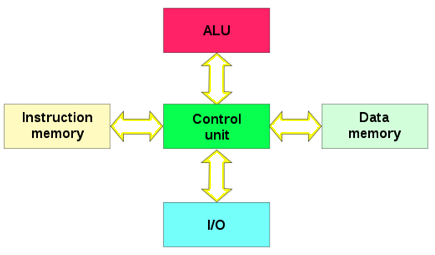
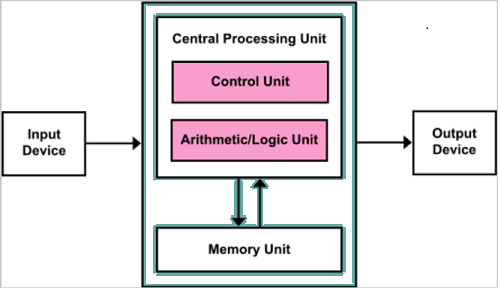
Laajennetaanpas hiukan aiemmassa kurssiosuudessa esiteltyä tietokonejärjestelmän yleistä arkkitehtuurikuvausta.
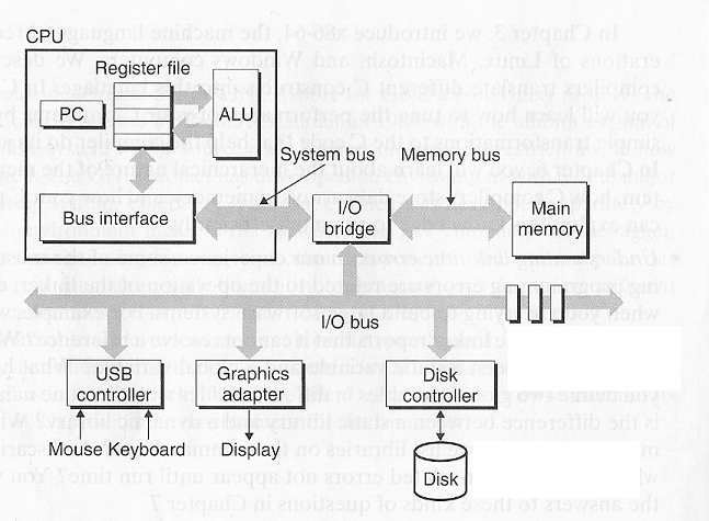
Suorittimen sisäisessä arkkitehtuurissa on erotettavissa viisi osaa:
1. Laskentayksikkö ALU (Aritmeettis-looginen yksikkö), joka suorittaa aritmeettiset ja loogiset operaatiot rekistereissä olevalle datalle.
2. Ohjausosa (myös kontrolliyksikkö, engl. control unit) joka "ajaa" suoritinta (toteuttaa sekvenssilogiikan): ohjaa ja synkronoi suorittimen eri komponenttien ja osajärjestelmien toimintaa ja ohjaa järjestelmä- ja I/O-väyliä.
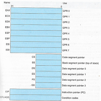
3. Rekisterit, jotka ovat suorittimen sisäinen muisti. Joka sisältäen käskyt ja niiden vaatiman datan sekä myös muuta informaation kuten suorittimen tilan. Kuvassa alla 8086-suorittimen rekisterikuvaus.
1. Laskentayksikkö ALU (Aritmeettis-looginen yksikkö), joka suorittaa aritmeettiset ja loogiset operaatiot rekistereissä olevalle datalle.
2. Ohjausosa (myös kontrolliyksikkö, engl. control unit) joka "ajaa" suoritinta (toteuttaa sekvenssilogiikan): ohjaa ja synkronoi suorittimen eri komponenttien ja osajärjestelmien toimintaa ja ohjaa järjestelmä- ja I/O-väyliä.
3. Rekisterit, jotka ovat suorittimen sisäinen muisti. Joka sisältäen käskyt ja niiden vaatiman datan sekä myös muuta informaation kuten suorittimen tilan. Kuvassa alla 8086-suorittimen rekisterikuvaus.
- Osa rekistereistä on yleiskäyttöisiä (GPR, general purpose register), joiden käyttötarkoitus on ohjelmoijan/kääntäjän valittavissa.
- Vaikka rekistereita saa käyttää vapaasti, on kone- ja assemblykielisten ohjelmien yhteensopivuuden parantamiseksi olemassa sovittuja käytäntöjä. Niistä lisää hetken päästä..
- Osalle rekistereistä on määritelty tarkoitus liittyen ohjelman suoritukseen.
- Käskyrekisteri (PC, engl. program counter / instruction pointer)
- (Tässä x86-arkkitehtuurissa) muistinosoitusrekistereitä (engl. segment registers) ja pino-osoitin (engl. Stack segment). Näiden rekistereiden ideana on osoittaa tiettyä käyttötarkoitusta varten varattuihin keskusmuistin lohkoihin.
- Suorittimen tilarekisteri, jonka bitit tilalippuina (engl. Condition codes) kuvaavat suorittimen tilaa, ohjauslogiikalle niin että mm. virhetilanteet ja laitekeskeytykset saadaan kiinni.
4. Muistit:
- Keskus/käyttömuisti (Randon Access Memory, RAM), joka pitää sisällään ohjelmankoodin ja datan.
- I/O-väylään kytketyt laitteet voidaan myös ajatella osaksi tätä muistia muistiinkuvatun I/O:n kautta. Esimerkki aiemmassa materiaalissa I/O-laiteajurit ja niiden rekisterit.
- Pinomuisti, eli suorittimelle (RAM-muistista) varattu muistalue, jota käytetään ohjelmien suorituksen apumuistina.
5. Suorittimen sisäiset väylät: Erilliset data-, käsky- ja osoiteväylät, jotka voivat myös liittyä osaksi järjestelmäväylää
- Esimerkkinä ulkoiset RAM-muistit tai lisäsuorittimet.
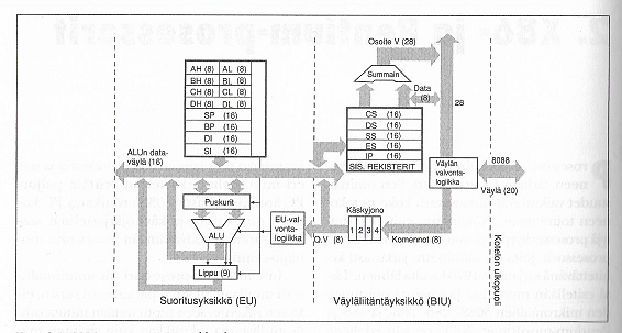
Esimerkki. "Alkuperäisen" IBM PC-tietokoneen 8088-prosessorin arkkitehtuuri.
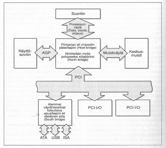
Esimerkki. Modernin PC:n I/O-väyläratkaisu. Hierarkiset I/O-sillat (north ja south bridge) kytkevät toisiinsa erinopeuksiset, -tyyppiset ja -kokoiset väylät.
Arkkitehtuurimallit
Historiallisesti ohjelmoitavien tietokoneiden suoritinarkkitehtuurit on jaettu Harvard- ja von Neumann-arkkitehtuurimalleihin, joiden toimintaperiaatteet luotiin jo 1930- ja 40-luvuilla. Ratkaisut erottaa toisistaan järjestelmäväyläratkaisu, eli (konseptuaalisessa) tietokoneen mallissa siinä miten ohjelma ja data haetaan muistista ja mitä siitä seuraa. Mallit on oleellista tuntea sen takia, että molempia on käytössä nykyäänkin.
1. Harvard-arkkitehtuurimallissa ohjelma ja data säilytetään erillisissä muisteissa ja molemmille muisteille on omat väylänsä. Tällöin myös käytetään erillistä muisti/osoiteavaruutta ohjelmamuistille ja datamuistille. Nyt siis muistiosoitteet eivät ole uniikkeja. Nykyään, kun puhutaan Harvard-arkkitehtuuria noudattavasta suorittimesta, niin itseasiassa tarkoitetaan suoritinta (engl. Modified Harvard Architecture) jossa on käytössä nämä erilliset muistiavaruudet.
Periaatteessa Harvard-arkkitehtuuri on nopea ratkaisu, koska muistiosoituksia voidaan tehdä yhtäaikaa molempiin muisteihin erillisten väylien kautta. Nykyesimerkki Harvard-arkkitehtuurista ovatkin sulautetut järjestelmät, joissa on erilliset muistit, ohjelmalle Flash-ohjelmamuistit ja datalle RAM-muisti.
2. von Neumann-arkkitehtuurimallissa käytetään yhtä samaa järjestelmäväylää sekä ohjelman käskyjen että datan hakemiseen samasta (fyysisestä) muistista. Se, että samassa muistissa säilytetään sekä ohjelmaa että dataa, itseasiassa mahdollisti alunperin yleiskäyttöisen tietokoneen kun ohjelmia voitiin käsitellä kuten dataa eli latailla muistiin, kirjoittaa päälle uutta koodia, tallentaa muistista massamuistiin, jne.
Huomataan, että von Neumannin mallissa kuvataan itseasiassa modernin tietokonejärjestelmän rakennuspalikat: suorittimessa erilliset ohjaus- ja suoritusosat, I/O-väylä ja erillinen muisti. Nyt, von Neumann-arkkitehtuurimallista seuraa yksinkertaisempi suorittimen toteutus, mutta ohjelmien suoritukseen aiheutuu viiveitä, koska ohjelmaa ja sen dataa ei voida noutaa loogisesti rinnakkain. Noh, tämän ongelman vaikutusta voidaan vähentää välimuisteilla ja muillakin keinoin, jota käsittelemme materiaalissa myöhemmin.
Nykyisin von Neumann-arkkitehtuuri onkin juuri yleiskäyttöisen tietokoneen malli, kuten modernit PC-työasemat. Tosin, nyt modernit suoritin- ja tietokonejärjestelmien arkkitehtuurit ovat välimuotoja molemmista malleista, joihin on poimittu ratkaisujen parhaat puolet.
y86-64 Suoritinarkkitehtuuri
Kurssilla käytämme opetustarkoituksiin kehitettyä suoritinta y86-64. Tämä prosessori on (todella paljon) riisuttu versio PC-koneissa nykyään yleisestä x86-prosessoriarkkitehtuurista, mutta sen käskykanta ja sisäinen toiminta ovat tarkoituksella hyvin samankaltaisia. Prosessoriarkkitehtuurina moderni x86-perhe on varsin pitkälle kehitetty tuhansien insinöörien vuosikymmenien työn tulos, jota ei ihan peruskurssin tuntimäärillä läpikäydä..
Kuvassa alla yksinkertaistettu y86-64 prosessorin arkkitehtuuri. Yleisesti y86-64 prosessorissa on siis ALU, yleiskäyttöisiä ja myös käyttötarkoitukselta määrättyjä rekistereitä, kolme prosessorin tilabittiä ja keskusmuisti. Muisti on (von Neumann-arkkitehtuurin mukaisesti) jaettu ohjelmien ja datan kesken ja lisäksi osa siitä jaetaan pinomuistille. Ohjausosan logiikkaa käymme myös materiaalissa läpi siltä osin kun se liittyy ohjelmien suoritukseen.
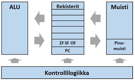
y86-64 prosessoriarkkitehtuuri yleisesti:
- Arkkitehtuuri on 64-bittinen, josta seuraa että muistipaikat ja rekisterit ovat 64-bittisiä.
- Näin ollen sanan pituus on 64 bittiä.
- Lukuesitys on 2-komplementti ja MSB-bitti on merkkibitti.
- Tavujärjestys on little endian, eli vähiten merkitsevä tavu ensin.
- Bittijärjestys on big endian eli eniten merkitsevä bitti ensin.
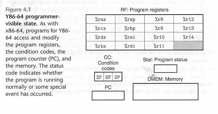
Kuvassa alla ohjelmoijalle näkyvä prosessorin ja muistin tila.
Rekisterit
Kun siis ohjelmoimme assemby-kielellä, yleiskäyttöiset rekisterit ovat konekielen muuttujien muistipaikkoja. Lisäksi suorittimen toiminta tarvitsee joukon omia rekistereitään.
y86-prosessorissa on useita rekistereitä, joista osalle on määrätty käyttötarkoitus:
- Yleiskäyttöisiä (GPR):
%rax,%rcx,%rdx,%rbx,%rsi,%rdi,%r8-%r14 - Pinon alkupään osoite:
%rbp - Pinon osoitinrekisteri:
%rsp - Tilarekisteri STAT: Ohjelman suorituksen tila, kts alla.
- Hox! Tämä rekisteri on eri asia kuin suorittimen tilabitit.
- Ohjelmalaskuri (Program counter, PC) sisältää seuraavan suoritettavan käskyn muistiosoitteen.
Hox! Assembly-kielessä
%-merkki ilmaisee, että kyse on ohjelmallisesti käytettävästä rekisteristä. Rekisterien nimet noudattavat x86-prosessoriperheen nimeämiskäytäntöä.Suorittimen ja ohjelman tila
Assembly/konekielisen ohjelman toiminta perustuu prosessorin tilaa osoittavien tilalippujen/bittien arvon tarkasteluun. Tilabittejä, joista käytetään yleisesti nimitystä tilaliput, varten on varattu erillinen tilarekisteri:
- Tilalippu asetetaan, kun suoritin saa keskeytyksen.
- Konekielisen ohjelman ehdollinen toiminta (vertailuoperaattorit, hyppykäskyt, jne) perustuvat tilarekisterin bittien arvon vertailuun.
- Käskyn seurauksena aiheutuva virheellinen toiminto merkitään asettamalla tilalippu.
Yleisesti, konekielten käskyjen suorituksen seurauksena prosessorin tilaliput muuttuvat ja sitten seuraavat käskyt reagoivat tilalippuihin, Tällä tavoin saadaan konekieliseen ohjelmaan luotua sen logiikka käyttäen tilalippuja.
y86:sessa on kolme tilalippua/bittiä (engl. condition codes, CC):
1.
1.
ZF (zero flag): Ilmaisee oliko edellisen ALUn suorittaman operaation tulos 0. Usein tätä lippua käytetään yhtäsuuruuden toteamisessa.- ZF=0, tulos erisuuri kuin 0
- ZF=1, kun tulos on 0
Esimerkiksi positiivisen ja positiivisen luvun vähennyslasku
  01111111
- 01111111
  --------
  00000000 ZF=1, koska tulos on 0
2.
SF (Sign flag): Oliko edellinen ALUn operaation tulos negatiivinen? - SF=0, tulos > 0
- SF=1, tulos < 0
Esimerkiksi positiivisen ja negatiivisen luvun yhteenlasku
  00001111
  10000001
  --------
  10010000 Nyt merkkibitti MSB on 1, joten tulos negatiivinen -> SF=1
3.
OF (Overflow flag): Ilmaisee tapahtuiko operaatiossa ylivuoto, joka tarkoittaa sitä, että laskutoimitus ei mahdu tulosrekisterin lukualueeseen eli on isompi kuin sanan pituus.- OF=0, ei ylivuotoa
- OF=1, ylivuoto tapahtui
Lasketaan yhteen kaksi positiivista lukua:
  01111111
  01111111
  --------
  11111110 Tulos ei mahdu positiiviseen lukualueeseen, MSB = 1 -> OF=1
           Lisäksi -> SF=1

Lasketaan yhteen kaksi negatiivistiä lukua:
  10000001
+ 10000001
  --------
 100000010 Nyt MSB =1, mutta se leikkautuu pois
  00000010 Tulos on positiivinen luku -> OF=1
Tilarekisterissä (status code,
STAT) on y86:n ohjelman suorituksen tila, joka voi olla:AOK: Kaikki okHLT: Prosessori pysähdyksissäADR: Osoitettiin väärään muistiosoitteeseenINS: Käskyssä virhe / väärä käsky
Oikeissa prosessoreissa tilabittejä on useita muitakin, esimerkkinä 8086:n 16-bittinen tilarekisteri. Usein törmää oikeissa suorittimissa "muistinumerona" (Carry-lippu) käytettävälle "ylimääräiselle" bitille, jonka avulla voidaan suorittaa sanan pituuden ylittäviä operaatioita oikein.
Esimerkiksi. 8-bittinen lukualue + carry-lippu ikäänkuin antaa ohjelmalle käyttöön 9 bittiä. Mutta, carry-lipun tilaa voi ainoastaan lukea, ei itse muuttaa. Konekielissä on usein myös erillisiä käskyjä, jotka reagoivat carry:n tilaan.
Muistin osoitusmuodot
Assembly/kone-kielessä voidaan käskyn operandeja esitellä ja niillä osoittaa dataa / muistia eri tavoin. Käskyn tulkitsemisen yhteydessä prosessori laskee osoitusmuodosta, mistä käskyn tarvitsema data löytyy.
y86-64:sessa on kolme osoitusmuotoa:
- Suora osoitus (Immediate) kun käskyn operandi on vakioarvo:
$numero. Esimerkiksi luvut$1,$-13tai$0x1F. - Esimerkki: talletetaan kymmenjärjestelmän luku -13 rekisteriin %rsi käskyllä
irmovq $-13,%rsi. - Rekisteriosoitus (Register) jossa käskyn operandi on rekisterin kulloinenkin sisältö:
%rekisteri. - Yleensä ALU voi tehdä operaatioita vain rekistereissä olevalle datalle, joten se on ensin talletettava johonkin rekisteriin.
- Esimerkiksi talletetaan rekisterin %rax arvo rekisteriin %rbx käskyllä
rrmovq %rax,%rbx. - Epäsuora osoitus (Memory) jossa operandi haetaan jonkun rekisterin arvon osoittamasta muistipaikasta. Tässä rekisteri merkitään sulkeilla:
(%rekisteri). - Sulkeiden edessä voi vielä olla numero
n(%rekisteri)(base + displacement), jossa tapauksessa osoitetaan muistipaikkaarekisterin arvo +- n, jossa on voi olla positiivinen tai negatiivinen. (Tätä ominaisuutta käytetään tyypillisesti pinomuistin lukemisessa.) - Esimerkiksi haetaan muistista data-arvo muistipaikasta %rax:n arvo ja tallennetaan haettu arvo rekisteriin %rbx käskyllä
mrmovq (%rax),%rbx. - Esimerkiksi haetaan muistista data-arvo laskemalla %rax:n arvo-16 ja tallennetaan haettu arvo rekisteriin %rbx käskyllä
mrmovq -16(%rax),%rbx. - Tätä osoitusmuotoa vastaa C-kielen osoitin eli (%rekisteri) voisi olla C-kielessä uint64_t *rekisteri.
Keskusmuisti
y86-prosessorissa on keskusmuistia noin neljä kilotavua. Muistipaikan koko on tietenkin sanan pituus, eli 64 bittiä, eli 8 tavua.
Muistetaan tässä bitti- ja erityisti tavujärjestys, joka on vähiten merkitsevä tavu ensin. Tämä siis poikkeaa C-kielen osuudessa käytetystä määrittelystä!
Lopuksi
Tämän luentokappaleen johdantomateriaali esitti pohjatiedot myöhemmin kurssilla käsiteltävään suorittimen ja tietokonejärjestelmän toiminnan ymmärtämiseen, toiminnan yleisiin ongelmiin ja niiden ratkaisuihin.
Anna palautetta
Kommentteja materiaalista?