Kuten teit edellisessä sessiossa, lataa virtuaalikone. Lataa virtuaalinen levykuva (.ova-tiedosto) joko lataamalla Onedrivesta tai käytä Windows File Exploreria ladataksesi sen sijainnista
\\kaappi\Virtuaalikoneet$\VMware\TKJ_Harjoitukset_2023\TKJ2023.ova (Luultavasti nopeampi kuin edellinen vaihtoehto.)HUOM: Tämä on päivitetty versio.
Kurssin SensorTag-projekti
Asennus
Seuraavaksi sitten tuodaan kehitysympäristöön kurssin projektiaihio. Lataa .zip joka sisältää tyhjän projektin ja ja tuo tyhjä projekti työtilaasi ( katso sessio 1 ohjeet)
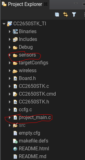
Lopuksi lisäämme joitakin uusia tiedostoja ja kirjastoja. Tiedostot voi ladata tästä Github-projektista. Lataa kaikki github-projectin tiedostot tietokoneellesi. Sen jälkeen tuo seuraavat tiedostot projektiisi.
- project_main.c
- sensors-hakemisto (kaikki tiedostojen pitää olla sensor-kansiossa. Voit raahata ja pudottaa kanssiot projektiin)
Huomio! tiedosto
project_main.c tulee olemaan päätiedostomme, joten poista rakennuksesta (Remove from build) kaikki muut tiedostot, joissa on main funktio.Tehtävä 1 - Painonapit ja ledit
Lähdetään liikkeelle ihan peruasioista ja katsotaan luentomateriaalin avulla miten saadaan painonapit ja ledit käyttöön laitteessamme. Materiaalit löytyvät luentokappaleesta 16. "Input / Output".
Tässä tehtävässä käytetään toista SensorTagin painonappia asettamaan punainen ledi päälle / pois. Tarvitsee siis:
- Esitellä RTOS:n globaalit muuttujat painonappi- ja ledipinneille.
- Määritellä pinneille oikeat konfiguraatiot.
- Laatia keskeytyksenkäsittelijä painonapille.
- Ottaa pinnit mukaan ohjelmaan
main-funktiossa.
Video Tehtävä 1.
Hox! Huomatkaa että Sensortag-laitteessa on useampia ledejä kuin mitä ohjelmassa voimme käyttää. Kurssilla meitä siis kiinnostavat laitteen pohjassa (punaisen kumisuojuksen raossa) näkyvät kaksi ohjelmoitavaa lediä, punainen ja vihreä. Lisäksi laitteessa on näytön ja debuggerin välissä debuggerin kaksi lediä, joita emme voi ohjelmallisesti käyttää.
Tehtävä 2 - Anturidatan lukeminen
Tässä tehtävässä otamme i2c-väylän käyttöön ohjelmassa ja luemme sitä kautta valoisuusanturilta OPT3001 mittausarvoja. Testauksen vuoksi tulostetaan vielä mitatut anturiarvot debuggerin kautta kehitysympäristön konsoli-ikkunaan. Materiaalit löytyvät luentokappaleista 17. "Sarjaliikenne", 20. "SensorTagin oheislaitteet" ja 8. "C-kielen syöte ja tulostus"
Tehtävässä:
- Otetaan
main-funktiossa i2c-väylä mukaan ohjelmaan. - Toteutetaan taskiin
sensorTaskseuraavat: - Alustetaan ja avataan i2c-yhteys.
- Alustetaan itse anturi toimintaan funktiolla
opt3001_setup(kirjaston otsikkotiedostoopt3001.hhakemistossasensors). - Luetaan anturilta dataa
opt3001_get_datafunktiolla ikuisessa loopissa. sensors-kirjaston tiedostoonopt3001.cfunktioonopt3001_get_datatarvitsee toteuttaa:- Määritellään i2c-viestirakenne, jolla OPT3001-anturin kanssa kommunikoidaan. Tarvittavat tiedot löytyvät luentokappaleesta 20. "SensorTagin Oheislaitteet".
- Tarvitaan oikea koko viestirakenteen puskureille
txBufferjarxBuffer. (Tehtävän koodissa kommentoitu ulos). - Anturin i2c-osoite viestirakenteen jäseneen
.slaveAddress. - Oikea rekisterin osoite lähetyspuskuriin
txBuffer. - Toteutetaan bittioperaatiot, joilla i2c-viestissä vastaanotetuista tavuista muodostetaan 16-bittinen rekisterinarvo
rxBufferiinvastaanotetuista tavuista. (Kts. bittioperaatiot luentokappale 5 sekä anturin käyttö kappale 20.) - Lasketaan saadusta 16-bittisestä rekisterinarvosta mittausarvo lukseina (ehkäpä käyttäen omaa harjoitustehtävävastausta?)
- Funktio palauttaa mittausarvon lukseina.
- Tulostetaan mittausarvo lukseina debuggerin kautta konsoli-ikkunaan.
Video Tehtävä 2.
Tehtävä 3 - Tilakone
Tässä tehtävässä tulee toteuttaa kuvan tilakone. Eli, aina kun on saatu uusi mittausarvo anturilta
sensorTaskissa, muutetaan ohjelmassa tila DATA_READY ja välitetään arvo globaalissa muuttujassa uartTasklle. Kummassakin taskissa tulostetaan mittausarvo debuggerin kautta konsoli-ikkunaan. Tarvittavat tilat sekä globaali tilamuuttuja että muuttuja mittausarvon välittämiseen ovat annettu valmiiksi koodissa.
Video Tehtävä 3.
Tehtävässä voisi kannattaa muuttaa ainakin uartTaskin sleep-periodi pienemmäksi, vaikkapa 100ms. Miksi?
Tehtävä 4 - Viestitys UARTilla
Tässä tehtävässä ideana on lähettää
uartTask:ssa debuggerin kautta konsoli-ikkunaan tulostettu merkkijono sarjaliikenne(UART)-yhteydellä kehitysympäristöön. Materiaalit löytyvät luentokappaleesta 17. "Sarjaliikenne".Tehtävä edellyttää sarjaportin kytkemistä kehitysympäristöön, josta annetaan videolla ohjeet IDE:lle. Voit tarkistaa myös Sessio 1 UART osa SensorTagin sarjaportin tunnistaa nimestä "XDS110 Class Application/User UART", jos porttia joutuu etsimään käyttöjärjestelmän työkaluilla.
- Windowsissa
COMn - Ubuntussa
/dev/tty/ACM0 - Muissa linuxeissa ehkä..
/dev/ttySn
Tehtävässä siis:
- Otetaan
main-funktiossa UART-toiminnallisuus mukaan ohjelmaan. - Taskissa
uartTaskalustetaan UART-yhteys parametreilla 9600,8n1. - Lähetetään
UART_write-funktiolla tehtävän 3. merkkijono sarjaliikenteen avulla kehitysympäristölle.
Video Tehtävä 4.
Hox! Kuten huomaatte, merkkijonossa rivinvaihtoon UART-sarjaliikenneyhteydellä ei enää riitäkään pelkkä \n (rivinvaihto, engl. line feed) vaan vaaditaan myös telanpalautus (engl. carriage return) mukaan, eli lisätään rivin loppuun rimpsu \n\r. Noh, tämä näitä historiallisia sarjaliikenneprotokolliin liittyviä asioita joiden kanssa joudumme elämään.
Tehtävä 5 - UARTin käyttö ulkoisen terminaalisovelluksen kanssa
Joskus on hyödyllistä liittää ulkoinen sarjaterminaali, jotta laitteen kanssa voisi olla vuorovaikutuksessa. Itse asiassa lopputyösi UARTGateway käyttää tätä yhteyttä. Tässä tehtävässä tarkistamme, kuinka voimme käyttää ulkoista terminaalia (tässä tapauksessa
screen) nähdäksemme tiedot, jotka SensorTag UART kirjoittaa. Saat tietoa screenistä tästä opetusohjelmastaTehtävässä siis:
- Katkaise terminaali CCS Studiosta.
- Debuggaa projektiisi.
- Ennen Resume pääohjelmaa avaa Linux-terminaali ja kirjoita
screen /dev/ttyACM0. - Sinun pitäisi nähdä UART-tulosteesi siellä.
- Poistuaksesi paina
Ctrl-Aja sen jälkeenk-näppäintä.
Lopuksi
Näin. Nyt on saatu Sensortagilla jo vilkutettua lediä, luettua sensoridataa ja kommunikoitua laitteesta ulkomaailman kanssa!